

Time:2021-05-31 Views:115
CNC machine tools are complex mechatronics products. Its maintenance is different from that of ordinary machine tools. In the maintenance process, several aspects must be comprehensively analyzed, the problem must be judged, and the cause must be found before processing. The following is a brief introduction of several methods often used in the maintenance process of CNC machine tools, and examples are given to illustrate.
For the maintenance of large-scale imported machine tools, the understanding of PLC programs cannot be completely based on the PLC statement structure and logic control. It is more about the mechanical structure of the machine tool and the full understanding of the machining process. Mastering these is often necessary to analyze the PLC program. Can play a multiplier role.
Example 1: A five-axis linkage CNC boring and milling machine produced by German MAHO company, the CNC system is a Philips system. In a transmission of the CNC program, due to improper handling, the transmission interface of the CPU board was burned out. Remove the CPU board and observe carefully, it is found that there are obvious burnt traces at the RS232 interface. Observe carefully under a magnifying glass, re-connect the disconnection: and replace an 8255 chip, which is newly installed on the machine tool, enter the machine parameters, and the machine tool returns to normal. The CPU board has been running so far and is in good operating condition.
Self-diagnostic function analysis
Example 2: A 16-meter vertical lathe produced by Wuhan Heavy Machine Tool Factory suddenly appeared alarm No. 43 (PLC is not ready for work) during a machining process. Read the fault code 34 in ISTACK, refer to the Siemens 840C diagnosis manual, the content is: Interface-DMP module startup error. Check all the DMP modules including the handheld unit, and found that the DMP module backplane connected to the ground console is not powered on. After consulting the electrical drawings, it was found that an air switch providing voltage was tripped, and the fault disappeared after closing it.
System reset method
Example 3: A CNC boring and milling machine from Czech SKODA company, the CNC system is Siemens 840C system. Alarm 43 (PLC is not ready to work) occurs during one processing. Refer to Siemens diagnostic manual. The cause of the failure is the hardware or software failure of the general data interface connection or the PLC machine data error or inconsistency with the user program. After power-on and reset, the fault phenomenon has changed. The PowerLED on the CNC system CSB board (central service board) is green and the out-puterrLED is red. The 43rd alarm still appears, and the X, Y, Z, U, and W axes of the machine tool are blocked, the hydraulic and static pressure systems cannot be established, and the servo drive system 611D series all have alarms. Analysis of the cause of the failure is that X, Y, Z, The U, W axis is blocked and the output error of the CSB board is related. Enter the system reset interface to reset the PLC, and run NCKPOWERON. At this time, the ANW-PLG file originally stored in the USER/PLC menu is loaded, and the No. 43 alarm is eliminated, but the CSB board The outputerrLED is still displayed in red, and the remaining alarms have not been eliminated. Analyze the cause of the failure, it may be caused by the confusion of the machine tool data during the power-on process, or it may be the failure of the CSB board hardware itself. The CSB board was removed for inspection after power off. No burnout was found. After cleaning, the alarm still exists after reinstalling it. According to the general reset method provided by Siemens, turn on the CSB board switch to the "I" position and power on again, set the system time/date, and load the machine data backed up on the MMC hard disk in MDD (Machine Data Dialogue), The system returns to normal. The CSB board out-outerrLED red light goes out, all alarms are eliminated, and the hydraulic system returns to normal. But X, Y, Z, U.W axis still can't move, check the information diagnosis, find that a subprogram SPF793 compiled by SKODA company is not running, transfer SPF793 to NCK to run the program, all faults are eliminated. The processing of this failure is a omni-directional one-time system installation. As for SPF793, it may be an installation subroutine compiled by SKODA, which must be run to unlock each interpolation axis of the machine tool.
Related News
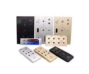
Related Products
Aluminum(Anodized) / Aluminum(Raw finish) / Brass / Plastic / Titanium / CNC Machining Case /
Our Work

Process
News
E-mail:dennis@7-swords.com


 Inquiry


