 EN


Custom CNC Machining · OEM / ODM Manufacturing
Custom CNC Machined Metal Support Bracket
A contoured support and mounting component developed around your drawing, assembly interface, material requirement, and finish specification.
Complex brackets are rarely defined by appearance alone. Hole relationships, cylindrical interfaces, datum surfaces, edge conditions, and surface quality can all affect assembly performance and manufacturing cost. PFTWORLD helps customers review these requirements before the machining route is finalized.
Built for Functional Interfaces, Not Just External Shape
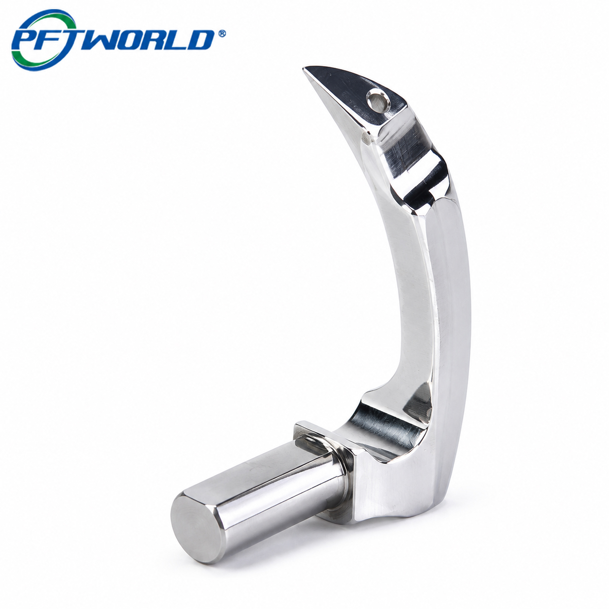
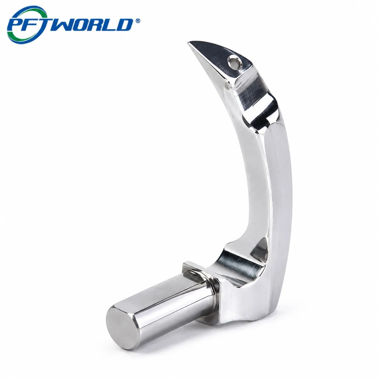
The pictured component shows the type of contoured metal geometry that may combine a mounting feature, a cylindrical boss or shaft interface, curved transitions, and cosmetic surfaces in one compact part. The final manufacturing process depends on the actual CAD model and technical drawing.
Where this design may be used
Depending on its confirmed function, a component of this type may serve as a support, pivot interface, positioning element, linkage component, sensor mount, or custom equipment bracket. These are potential use categories rather than claims about the supplied part.
During engineering review, the most important question is how the part locates and interfaces with neighboring components. A hole that appears simple may be a clearance feature, a locating feature, a bearing seat, or a threaded connection. Each function changes the required fit, datum strategy, inspection method, and finishing plan.
Visible design characteristics
- Contoured single-piece body with curved transitions
- Visible cylindrical projection or interface at the lower section
- Round opening and smaller opening near the upper section
- Stepped, radiused, and angled surfaces
- Reflective appearance requiring a defined cosmetic standard
Project Specifications Confirmed During Engineering Review
A photograph cannot establish production specifications. The following review structure helps turn a visual concept into a controlled, quotable CNC machining project. It also gives engineering, purchasing, quality, and production teams one shared reference before material is ordered or tooling is planned. This is especially useful when a part has a visible cosmetic surface but its real value depends on hidden alignment, fit, and repeatability requirements.
Geometry Review for a Reliable Machining Process
The same part can be easy or difficult to manufacture depending on how its features are dimensioned, oriented, held, and inspected. These image views highlight the engineering questions that should be answered before release.
From Drawing Review to Finished Component
A disciplined front-end review helps prevent avoidable quotation changes, rework, and assembly issues. PFTWORLD can evaluate the manufacturing route around the actual project information supplied by the customer.
Review the interfaces
Identify locating faces, hole patterns, shafts, fasteners, clearances, load paths, and cosmetic zones.
Plan the setup
Evaluate tool access, datum transfer, workholding, multi-face features, and the need for special fixtures.
Control the finish
Define machining marks, edge breaks, polishing, coating, masking, and dimensions after treatment.
Verify the result
Align inspection with the functional datums, critical dimensions, batch needs, and required reports.
Design Considerations That Can Affect Cost and Quality
Tool access and internal radii
Standard milling cutters leave radii in internal corners. Smaller cutters can reduce those radii, but they may be less rigid and slower in deep features. Where the mating design permits, use a larger radius or a corner relief instead of requiring a sharp internal corner.
Tolerances based on function
Do not apply a tight tolerance to every surface because the CAD model contains many decimal places. Identify the critical-to-quality relationships first, then define the position, profile, flatness, orientation, or fit requirements that the assembly actually needs.
Workholding and multiple setups
Curved outer surfaces, thin edges, and cosmetic faces can make clamping difficult. A stable workholding plan should be reviewed before production, especially when holes on different faces must maintain a controlled relationship.
Information to include in an RFQ
- 3D CAD model and controlled 2D drawing
- Material grade, temper, hardness, or condition
- Quantity for prototype, pilot, and repeat production
- Critical dimensions, datums, fits, and geometric tolerances
- Surface treatment, cosmetic zones, and masking requirements
- Inspection reports, certificates, sampling, and traceability needs
- Packaging, marking, cleanliness, and delivery requirements
Quality Planning for Fit, Appearance, and Repeatability
Inspection should follow design intent
Inspection is most useful when it measures the relationships that make the bracket work. A general visual check may confirm burr removal and surface condition, but it cannot replace verification of a critical hole position, bore diameter, axis relationship, or mounting-face orientation. The drawing should identify the datum features and the dimensions that require traceable results. This distinction helps avoid two common problems: paying for reports that do not address the true assembly risk, or discovering after delivery that a visually attractive part does not meet its functional interface.
Depending on the feature, inspection may use calibrated hand tools, gauges, a height gauge, an optical system, a surface roughness instrument, a fixture, or a coordinate measuring machine. The appropriate method depends on tolerance, accessibility, geometry, quantity, and the reporting level required by the customer.
Control the handoff from sample to production
A prototype can be approved by checking assembly fit and a limited set of dimensions. When the project moves to repeat production, the process should also address fixture stability, tool wear, finish consistency, inspection frequency, packaging, and revision control. An approved sample is a reference for the process; it is not a substitute for a complete production drawing.
For cosmetic parts, an approved visual sample or defect standard can be more useful than the word “polished” alone. Define the viewing distance, lighting, acceptable marks, edge condition, and protected areas before the order is released.
Material and Surface Finish Selection
The reflective appearance in the reference image does not confirm a material grade or finishing process. Selection should follow the service environment, mechanical requirements, interface wear, corrosion exposure, appearance target, and total manufacturing cost.
Material decisions
Aluminum may be considered where low mass and machinability are important. Stainless steel may suit corrosion-sensitive or robust mechanical applications. Steel can support stiffness, strength, or heat-treatment requirements. Brass, copper, titanium, engineering plastics, and other grades may be evaluated when conductivity, weight, wear, temperature, or chemical compatibility drives the choice.
These are material families, not a specification for the pictured part. The approved grade and condition should appear on the drawing or purchase documentation.
Finish decisions
“Polished” is not always a complete requirement. Clarify gloss, allowable tool marks, scratches, edge breaks, protected areas, coating or plating thickness, masking, and whether final dimensions apply before or after treatment. A clear cosmetic standard helps suppliers quote comparable work and helps receiving teams make consistent decisions.
Why Work with PFTWORLD for a Custom Bracket Project?
A capable machining partner should contribute more than a process name and a unit price. The value is in connecting design intent with a practical manufacturing and inspection plan.
A quotation should explain the manufacturing assumptions
For a complex support bracket, a useful quotation should make the important assumptions visible. These may include the material condition, number of setups, fixture or soft-jaw requirements, machining route, secondary finishing, inspection documents, packing method, and the quantity basis used for the price. When these assumptions are clear, buyers can compare quotations on more than unit price and identify where two suppliers are offering different scopes.
It is also useful to separate prototype requirements from repeat-production requirements. A first sample may need engineering feedback and a focused inspection report, while a recurring order may require a stable fixture, agreed cosmetic reference, batch documentation, and a change-control method. Discussing this transition at the RFQ stage helps reduce redesign risk when the part moves from approval to production.
Questions to ask before approving a supplier
Ask how the supplier will establish the part, where it will be clamped, which features will be completed in each setup, and how the critical interfaces will be inspected. Confirm whether finishing changes dimensions, whether the cosmetic requirement has an approved reference, and which documents will accompany delivery. A technically useful supplier should be able to identify the design features that create risk and explain practical alternatives without changing the intended function.
- Review of drawings, models, interfaces, and production requirements
- Support for milling, turning, drilling, boring, threading, and combined operations where appropriate
- Material and secondary-process evaluation based on the application
- DFM discussion focused on tool access, workholding, tolerance, and repeatability
- Inspection planning connected to critical features and customer documentation needs
- Support for prototype, low-volume, and repeat OEM manufacturing discussions
A clearer path from prototype to production
Prototype work may use flexible workholding and a limited inspection plan. Production requires repeatability, revision control, tool-life planning, finishing consistency, and a defined acceptance method. Discussing these differences early reduces the risk of redesigning the part or process after the first sample.
For more information about custom CNC machining, visit the PFTWORLD CNC machining parts page or send the project information through the contact and RFQ page.
Frequently Asked Questions
Can this bracket be customized to my drawing?
Which material should I choose?
What information is needed for a quotation?
Can a prototype process be used for production?
Send Your Bracket Drawing for Engineering Review
Share your 2D drawing, 3D CAD file, material and finish requirements, quantity, critical interfaces, and inspection expectations. PFTWORLD can review the project scope and confirm the appropriate machining and quotation requirements for the specific part.
Start a Custom CNC ProjectTable of Contents
- Built for Functional Interfaces, Not Just External Shape
- Project Specifications Confirmed During Engineering Review
- Geometry Review for a Reliable Machining Process
- From Drawing Review to Finished Component
- Design Considerations That Can Affect Cost and Quality
- Quality Planning for Fit, Appearance, and Repeatability
- Material and Surface Finish Selection
- Why Work with PFTWORLD for a Custom Bracket Project?
- Frequently Asked Questions
- Send Your Bracket Drawing for Engineering Review