 EN


CNC Machining Design & RFQ Guide
How to Prepare Complex CNC Machined Parts for DFM and RFQ Review
A practical guide for engineers, OEM buyers, and procurement teams preparing complex custom CNC machined parts for quotation, production, and inspection.
Key principle: A part should not only be machinable. It should also be repeatable to produce, clear to inspect, and straightforward to quote.
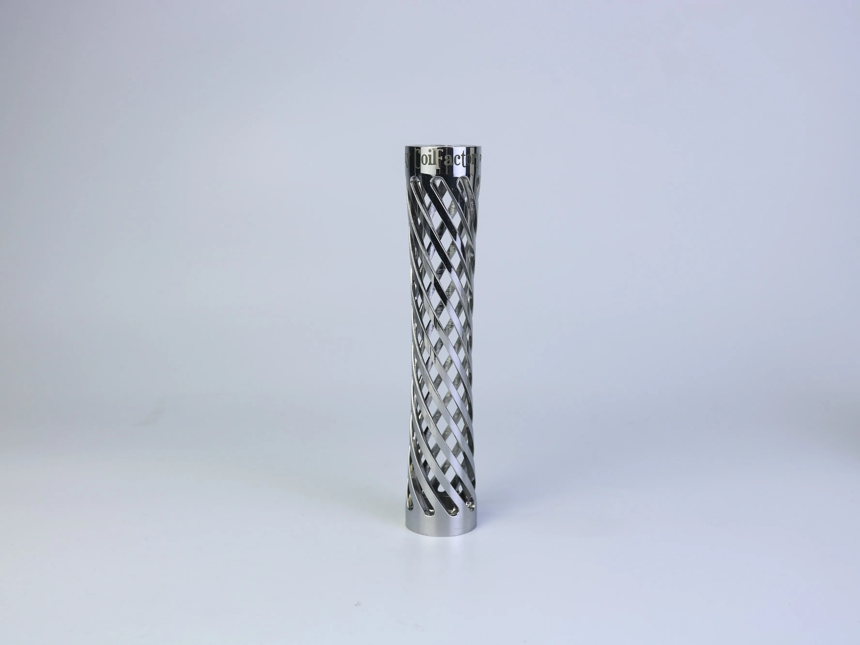
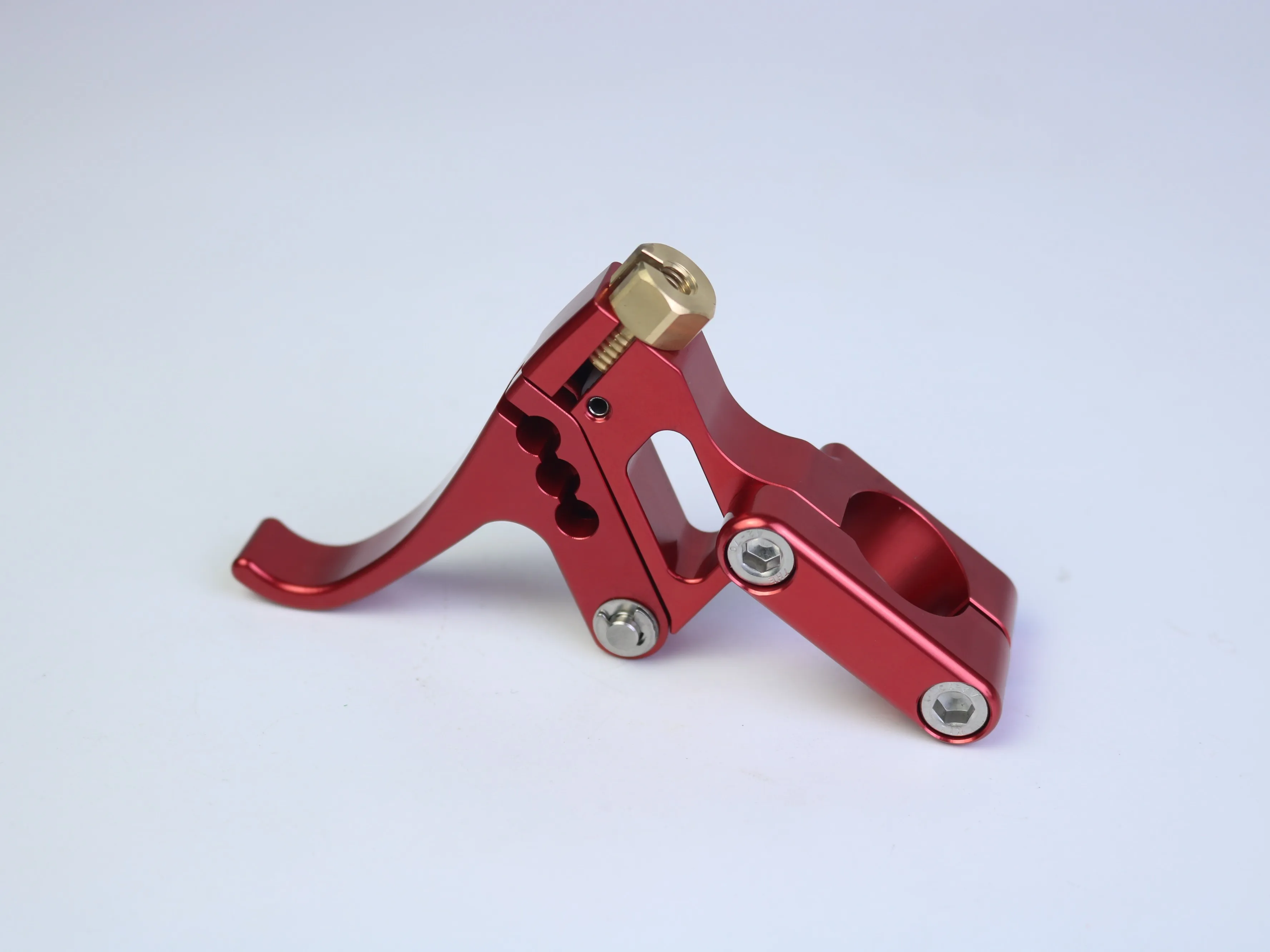
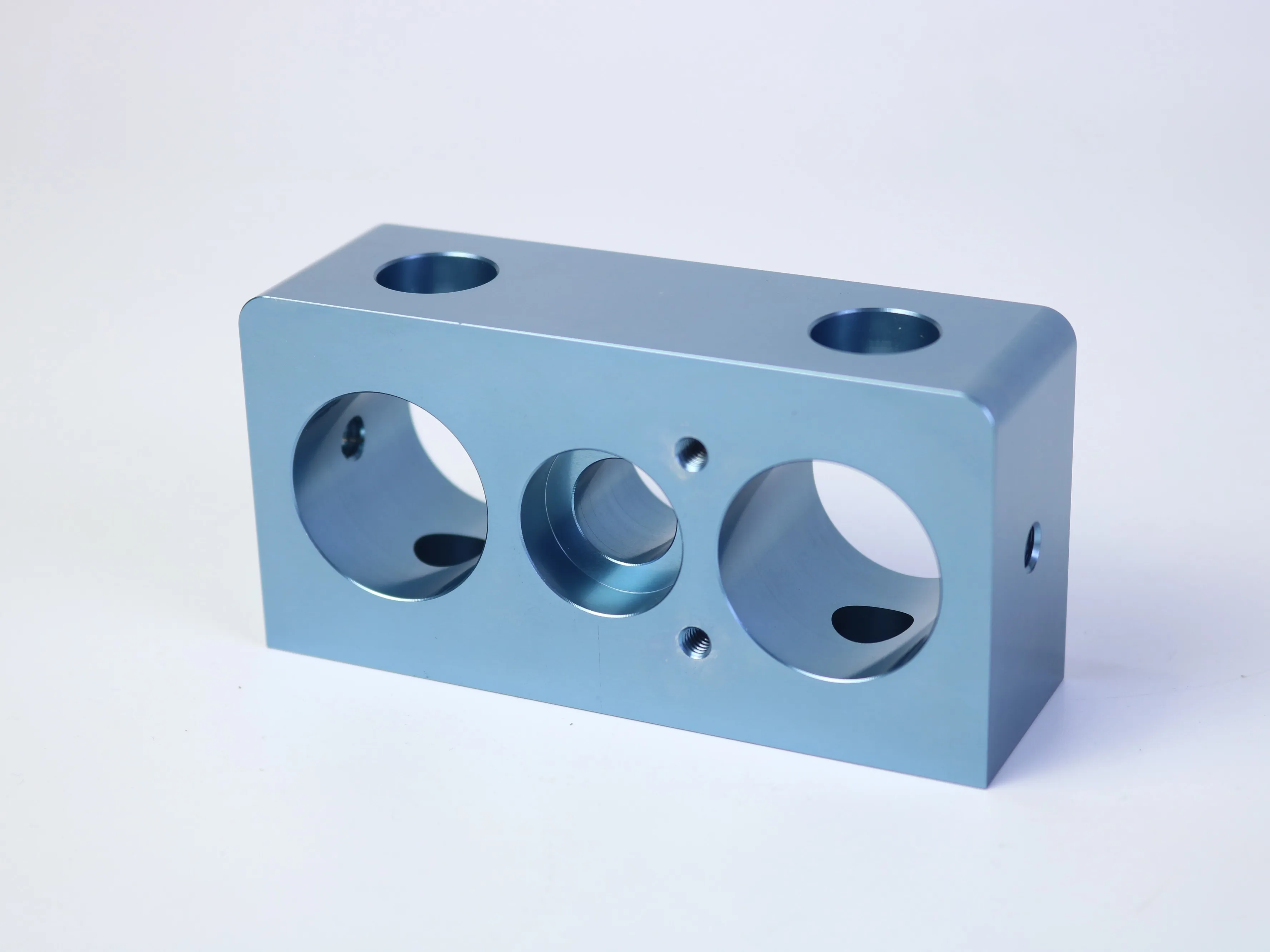
Complex CNC machined parts can look simple in a CAD model but become difficult to quote and manufacture when the design combines intersecting holes, deep cavities, thin walls, tight fits, multiple setups, or decorative finishes. A cylindrical sleeve with repeated openings, a contoured bracket, and a multi-hole block may all be feasible, but each requires a different review of tool access, workholding, inspection, and finishing.
The most useful question is not simply, “Can this part be machined?” It is: Can the part be machined consistently, inspected objectively, and quoted without hidden assumptions? The answer depends on how clearly the design intent is translated into manufacturing and quality requirements before an RFQ is sent.
Before requesting a price, identify the features that control risk: functional datums, mating holes, tool access, setup count, tolerance-critical surfaces, material condition, finishing requirements, inspection scope, quantity, revision, and delivery expectations.
1. Start with function, not appearance
Product images are useful for discussing geometry, but they cannot define a manufacturing specification. The three reference components shown here are different forms of complex metal geometry. Their appearance alone does not confirm material grade, dimensions, tolerances, function, pressure rating, or the process used to produce them.
Functional features
Identify bearing seats, sealing faces, pivot bores, mounting patterns, locating shoulders, and interfaces that must mate with another part.
Supporting features
Separate non-critical pockets, clearance holes, cosmetic steps, and lightening openings from dimensions that control assembly or performance.
Manufacturing features
Allow for stable fixturing, tool clearance, deburring access, practical chamfers, and edge breaks that support consistent production.
For critical functional features, provide explicit dimensions, datums, geometric tolerances, and inspection requirements where they are necessary. Supporting features still need sensible definition, but they may not justify the same tolerance or inspection burden. Manufacturing features are often overlooked because they do not appear in the final function; however, they can determine whether the part can be held, machined, deburred, and measured reliably.
2. Review tool access and internal geometry early
CNC cutting tools are not infinitely flexible. End mills and drills are generally cylindrical, and the tool must approach a feature with adequate clearance. Internal corners produced by a rotating tool therefore normally require a radius rather than a perfectly sharp corner. Deep cavities and narrow slots may also require smaller, longer tools, increasing the risk of deflection, vibration, poor chip evacuation, and inconsistent surface finish.
During a DFM review, ask:
- Can the cutter reach the bottom of each pocket without excessive overhang?
- Are internal radii compatible with available tools?
- Could a thin rib or unsupported wall deflect under cutting forces?
- Will side and underside features require a second or third setup?
- Could the fixture cover a datum or restrict inspection of a critical surface?
If a sharp internal corner is not functionally necessary, adding a practical radius can simplify programming and reduce the need for a small cutter. Do not apply a universal radius or wall-thickness rule without considering the material, part size, tool selection, and actual supplier process. The correct value should be agreed during a geometry-specific DFM discussion.
3. Treat holes, threads, and bores as a system
A hole is rarely just a circle on a face. Its manufacturing difficulty depends on diameter, depth, direction, location, tolerance, finish, intersection with other holes, and how it will be inspected. This is particularly important for interface blocks, manifold-like components, and parts with several intersecting bores.
For each important hole or bore, define:
- Size and tolerance: state the nominal diameter and the tolerance that the function actually requires.
- Depth and direction: identify through holes, blind holes, angled holes, and any minimum usable depth.
- Location: relate the feature to a functional datum or mating pattern.
- Edge condition: specify chamfers, counterbores, countersinks, and edge breaks.
- Thread definition: include the thread standard, size, class, and usable thread depth where applicable.
- Process and cleanliness: state whether reaming, boring, interpolation, deburring, cleaning, or passage inspection is required.
For a part with internal passages, the RFQ should also state whether passages must be pressure-tested, cleaned, plugged, or inspected. A photograph cannot establish these requirements, so they must come from the drawing and application.
4. Plan the machining strategy around datums and setups
Many complex parts are not difficult because of one feature; they are difficult because several features must remain related across multiple orientations. Each repositioning creates another opportunity for datum-transfer error, fixture variation, or mismatch between features cut in different setups.
A practical process review should map the primary, secondary, and tertiary datums; identify the first setup; show which surfaces are created in each clamping; and confirm when critical features can be machined together. Inspection access should be considered at the same time. A feature that is easy to cut may be difficult to measure after the next operation.
Indexed 3+2 or continuous multi-axis machining may improve access and reduce manual repositioning, but it is not automatically the lowest-cost solution. A well-oriented design may be more economical on a conventional mill. A part with angled faces, repeated side features, or tight relationships across several orientations may benefit from a multi-axis approach. The decision should be based on access, setup count, tolerance relationships, and quantity—not on the number of axes alone.
5. Specify tolerances by function
One common cause of unclear CNC quotations is a drawing that applies tight tolerances everywhere without identifying which dimensions control performance. Tight tolerances can require additional finishing passes, special tooling, more detailed inspection, temperature control, or a different process route.
Tolerance values should come from the design function, applicable standards, and the selected supplier’s verified capability. Avoid copying a generic tolerance table into a drawing without checking worst-case assembly conditions.
6. Separate material evidence from appearance
A polished silver surface may look like stainless steel, while a red or blue surface may suggest anodized aluminum. Neither appearance proves a material grade or finishing process. Specify material by engineering requirement and confirm it through the RFQ and material documentation.
Review strength and stiffness, corrosion exposure, weight, thermal behavior, machinability, tool wear, stock availability, surface treatment, and traceability. If the part will be anodized, plated, polished, or coated, state whether dimensions apply before or after finishing. Define masking areas, cosmetic faces, color expectations, and functional surfaces that must remain within tolerance after treatment.
7. Build an RFQ that allows comparable quotations
A useful CNC machining RFQ should contain more than a 3D file. The goal is to give each supplier the same technical assumptions so that the resulting offers can be compared fairly.
If a supplier must guess the material, quantity, finish, or inspection scope, quotations may differ because they are based on different assumptions. A complete RFQ reduces the risk of comparing incomplete offers instead of comparable manufacturing plans.
For repeat programs, define how revisions will be controlled. The drawing revision, CAD revision, finish specification, inspection plan, and packaging instruction should point to the same release. If a design changes after prototype approval, identify which dimensions, tools, fixtures, inspection records, and existing stock may be affected. This simple change-control step helps prevent a supplier from manufacturing to an outdated file while the buyer is reviewing a newer drawing.
8. Ask suppliers how they will control risk
Price is only one part of supplier evaluation. For complex custom CNC machined parts, ask each supplier to identify the proposed machining process, number of setups, tool-access concerns, workholding strategy, inspection points, burr and chip controls, material verification, finishing controls, and documentation included in the quoted price.
A technically useful supplier should be able to explain the relationship between geometry, process choice, inspection, and quotation. For project-specific review, buyers can explore PFTWORLD’s CNC milling service and custom CNC machining parts service pages, then confirm current capabilities directly during RFQ discussion.
Common mistakes that create avoidable cost
- Sending only a rendered image: an image communicates appearance but cannot define datums, tolerances, material, or inspection.
- Making every feature “precision”: unnecessary tight tolerances can increase machining and inspection effort without improving assembly.
- Ignoring finishing allowances: coating or anodizing can affect dimensions, masking, edge appearance, and color consistency.
- Designing inaccessible geometry: deep cavities, sharp internal corners, hidden cross-holes, and thin unsupported walls may be expensive or unstable to machine.
- Leaving inspection undefined: if a hole pattern, bore, or sealing face is critical, state how it will be measured and against which datum.
Frequently asked questions
Can a complex CNC part be quoted from a 3D model alone?
A 3D model supports an initial feasibility review, but it may not communicate material, tolerance, surface finish, thread standard, inspection, or revision requirements. A current 2D drawing is important when those details affect function or acceptance.
Does a complex part always require 5-axis CNC machining?
No. The process depends on feature orientation, tool access, datums, setup count, tolerance relationships, and quantity. A well-planned 3-axis process may be suitable for one design, while another may benefit from indexed or simultaneous multi-axis machining.
Should all internal corners be sharp in the CAD model?
Not unless the function specifically requires it and the manufacturing process can support it. Rotating tools normally create internal radii, and a practical radius can improve tool access and reduce unnecessary machining difficulty.
How should buyers compare CNC quotations?
Compare the assumptions behind each price: material, quantity, setup strategy, tolerances, finish, inspection, documentation, packaging, delivery condition, and deviation policy. A lower unit price may exclude requirements included in another quotation.
What should I send to a CNC machining supplier?
Send the latest 2D drawing, 3D CAD file, material and finish requirements, quantities, critical inspection details, delivery expectations, and required quality documents. Ask the supplier to return DFM questions before production begins.
Make manufacturability part of the RFQ
Reliable custom CNC machined parts start before cutting begins. Share the current drawing and 3D CAD file with PFTWORLD for a project-specific discussion of manufacturability, machining route, finishing, inspection, and quotation requirements.
Discuss your CNC machining projectTable of Contents
- 1. Start with function, not appearance
- 2. Review tool access and internal geometry early
- 3. Treat holes, threads, and bores as a system
- 4. Plan the machining strategy around datums and setups
- 5. Specify tolerances by function
- 6. Separate material evidence from appearance
- 7. Build an RFQ that allows comparable quotations
- 8. Ask suppliers how they will control risk
- Common mistakes that create avoidable cost
- Frequently asked questions
- Make manufacturability part of the RFQ