 EN


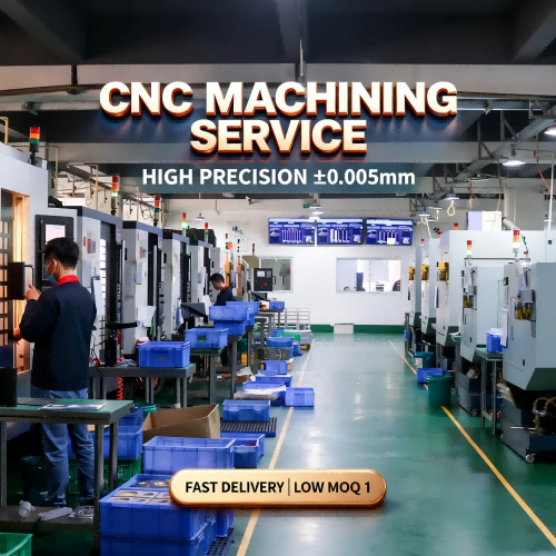
Custom CNC Machining | Engineering Support | B2B Manufacturing
Complex CNC Machined Components Built Around Function, Fit, and Repeatability
For flanged bodies, threaded housings, split fixtures, stepped parts, and other precision mechanical components, the right manufacturing result starts before machining. PFTWORLD supports buyers with practical design review, clear quotation scope, and custom CNC machining solutions for prototype and production requirements.
Custom Mechanical Components
A machined part is only successful when it performs in the assembly
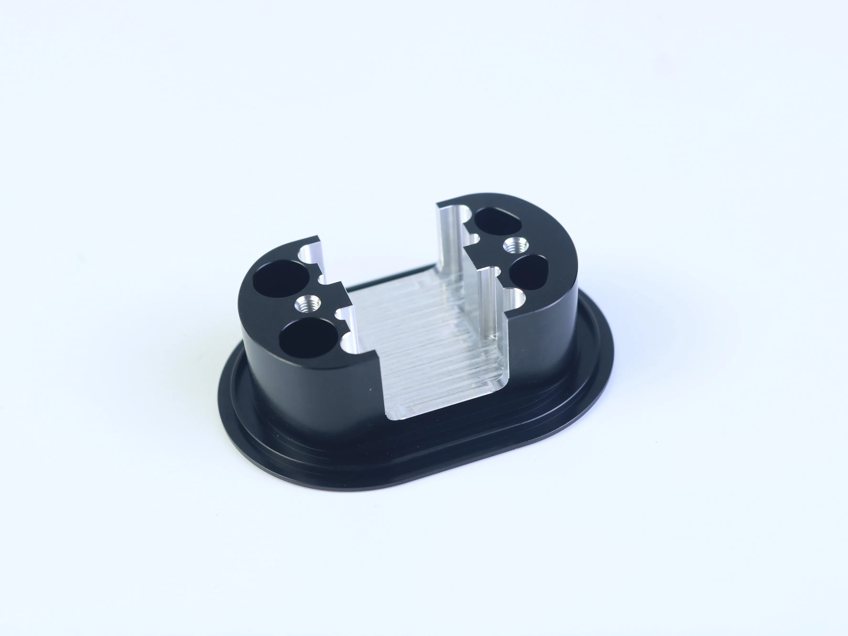
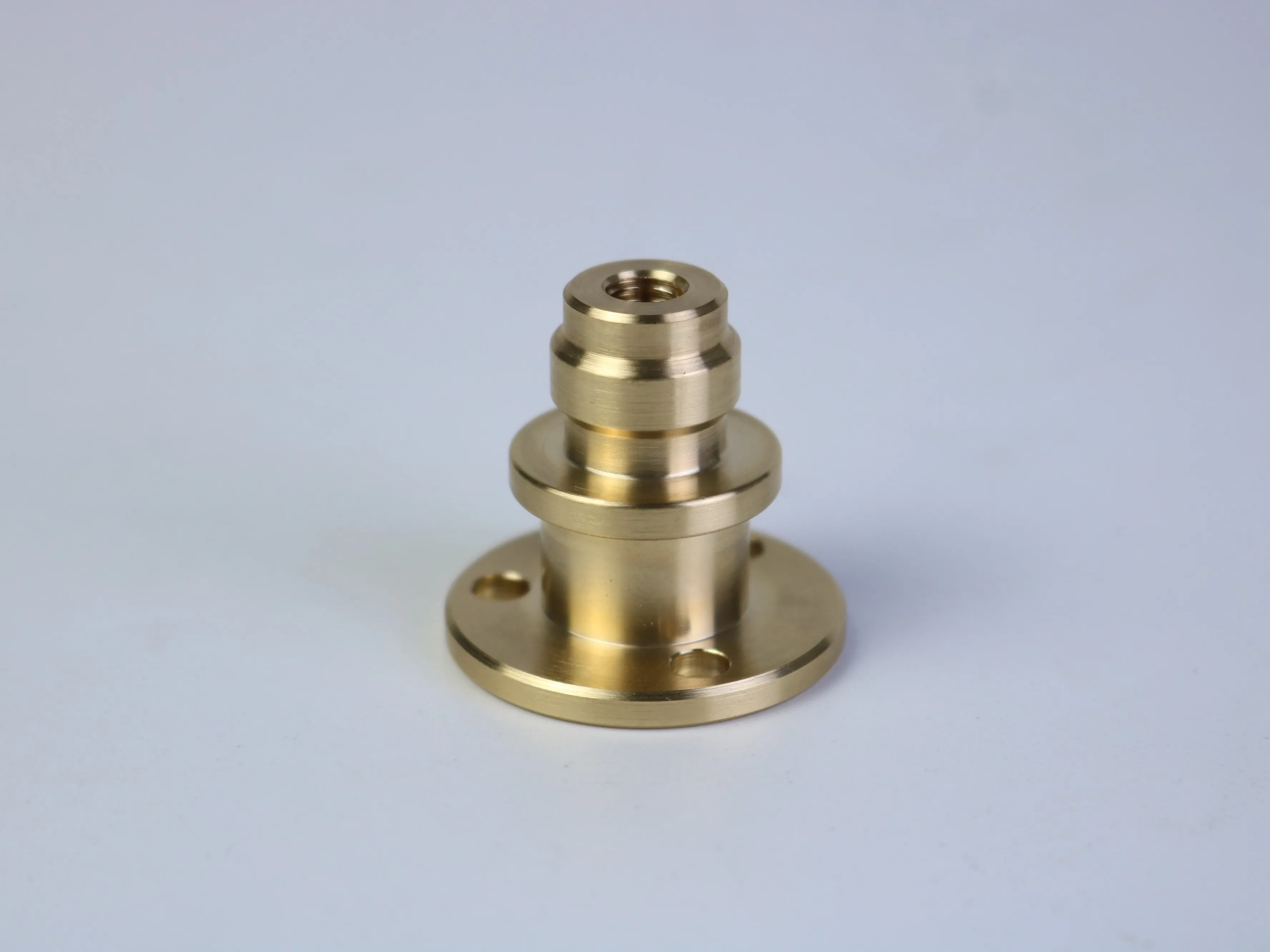
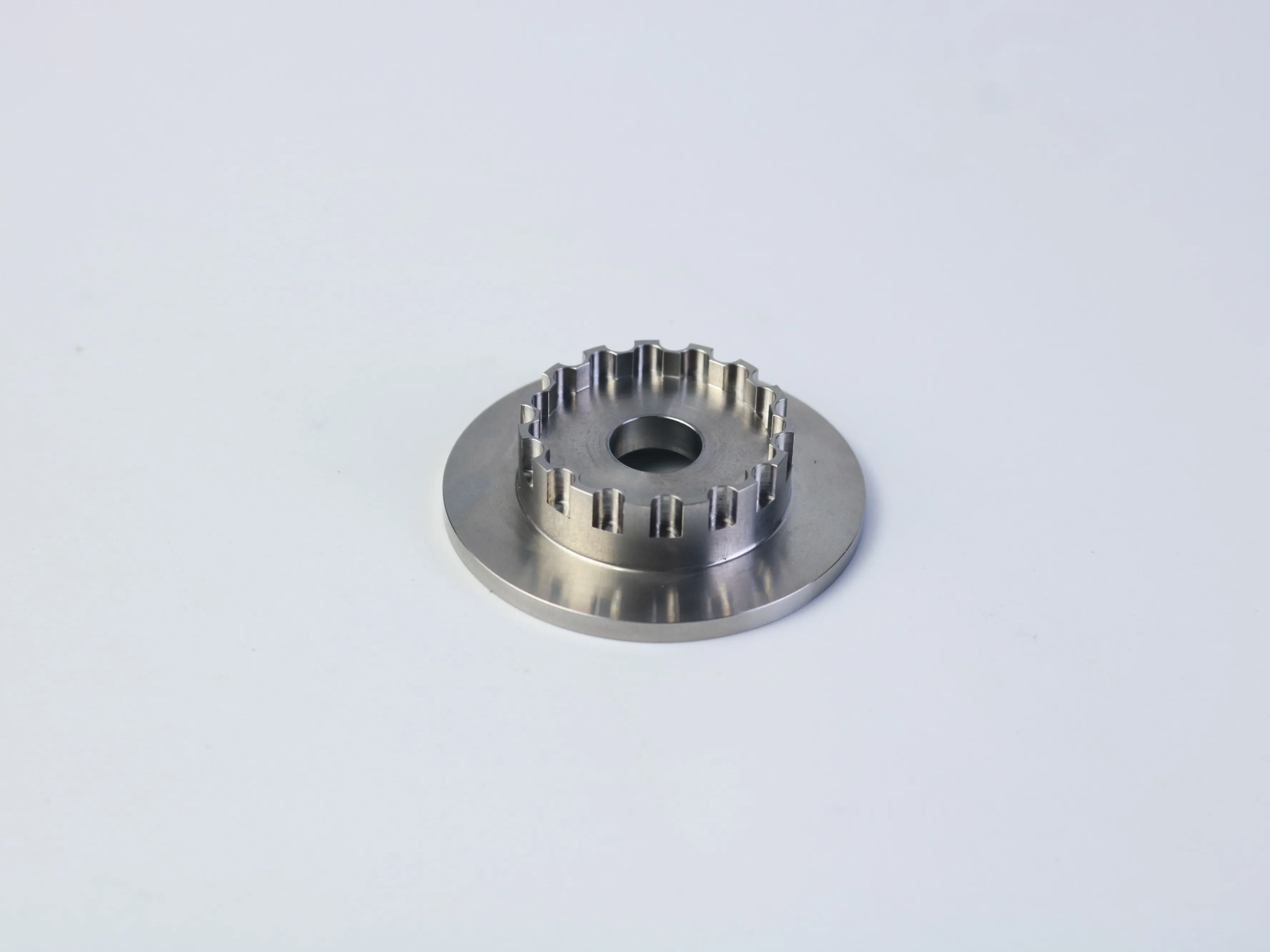
A complex CNC component may include a flange, stepped diameters, mounting holes, internal threads, slots, split openings, or repeated circular features. Each detail can be manufactured independently, yet the combination can create hidden risks: difficult workholding, limited tool access, accumulated setup error, inconsistent surface finish, or a quotation based on assumptions.
The most reliable approach is to review the design around three questions: Does the feature serve a clear function? Can the feature be reached and machined consistently? Can the requirement be inspected against a defined datum? This approach protects the design intent while reducing avoidable production complexity.
How geometry influences the CNC machining process
Rotational features such as outside diameters, shoulders, flange faces, and concentric bores may be suited to CNC turning. Non-rotational details—mounting patterns, slots, split openings, milled flats, and some threaded features—may require CNC milling, drilling, boring, tapping, or thread milling. A combined turning and milling route may be appropriate when a component contains both families of features.
The final process should be selected from the engineering requirements, not from the appearance of a sample image. Material grade, quantity, tolerance, surface finish, workholding, and inspection requirements can change the process plan significantly. During quotation, identify which surfaces control alignment, which holes receive fasteners or locating pins, and which dimensions are cosmetic rather than functional.
Engineering principle: A feature that is not functionally required should not create unnecessary tooling, fixturing, inspection, or finishing work. A feature that is functionally critical must be described precisely enough to protect fit and performance.
Five design checks that reduce manufacturing risk
1. Plan datums and setups around assembly
When a part requires more than one orientation, every repositioning step can introduce variation. Use functional datums that reflect how the part is assembled. A flange face may control axial position, while a central bore may control radial alignment. Hole patterns and slots should be related to the datum that actually governs the assembly, not simply to the nearest outside edge.
2. Use practical internal radii
Most milling cutters are cylindrical, so internal corners naturally receive a radius. Very small radii can require smaller tools, slower cutting conditions, more passes, and additional risk of deflection. Where the radius does not affect assembly, a practical fillet usually improves manufacturability. If a sharp internal corner is essential, identify it as a functional requirement and ask whether an undercut or alternative process is needed.
3. Define threaded features completely
A threaded hole should include the metric or inch standard, nominal size, pitch, fit or class where applicable, full thread depth, total hole depth, and blind or through condition. Excessive thread depth can add time and increase the risk of chip evacuation or tool breakage without improving the joint. The correct engagement depends on the material, fastener, load, and assembly design.
4. Apply tolerances by function
Tight tolerances should be reserved for surfaces that affect fit, motion, sealing, alignment, or load transfer. Applying precision callouts to every dimension increases machining and inspection effort without necessarily improving the final assembly. Use a clear datum structure and distinguish critical-to-function dimensions from general and cosmetic features.
5. Review deep features and thin walls
Deep pockets, narrow slots, and thin walls can increase vibration, tool deflection, heat, chip evacuation problems, and distortion. Review whether the feature can be opened, shortened, supported, or divided without affecting function. The actual limit depends on material, tool diameter, feature depth, workholding, and required accuracy, so use design ratios as a review prompt—not as a universal acceptance rule.
Surface finish and secondary operations
A black, silver, or brass-colored appearance in a photograph does not confirm a material grade or a specific surface treatment. The drawing should define the required machined roughness, edge-break or deburring standard, coating or treatment, masking areas, and whether dimensional requirements apply before or after finishing.
For functional parts, finish may affect friction, sealing, sliding, wear, corrosion resistance, or visual acceptance. Threads and mating surfaces may require special attention if a coating changes the final condition. If the finish is primarily cosmetic, state that clearly. If it protects performance, explain the function so the supplier can evaluate the appropriate process route.
From design review to a controlled manufacturing plan
A useful DFM review should not stop at identifying whether a feature is technically possible. It should connect the feature to a repeatable process route. For a component with a flange, bore, threaded holes, and a split or grooved region, the supplier should consider how the raw material will be held, which surfaces will be established first, and how the part will be located after repositioning.
This is where design and purchasing decisions meet. If the drawing calls for a very tight relationship between a bore and a hole pattern, the quotation should account for a common datum strategy and an inspection method that verifies that relationship. If a finish is applied after machining, the process plan should consider whether masking, dimensional allowance, or a final check is needed. If a part is difficult to hold without marking a cosmetic surface, the workholding method should be discussed before production.
Questions to ask during the engineering review
- Which surfaces will be used as the primary locating references?
- Can the critical bore, flange face, and hole pattern be controlled from a consistent datum system?
- Will the feature depth require a long-reach tool or a special cutting strategy?
- Are the threads accessible for machining, cleaning, gauging, and final assembly?
- Which dimensions must be measured after finishing rather than before finishing?
- Would a small design change remove a setup, tool change, or difficult inspection step?
These questions create a more useful conversation than simply asking whether a supplier can make the part. A capable manufacturing partner should be able to explain the effect of a proposed change, identify what remains uncertain, and separate confirmed requirements from assumptions.
How buyers can compare CNC machining quotations
Comparing the unit price alone can hide important differences. For complex machined parts, request each supplier to quote the same scope and to list any exclusions. A quotation should make it possible to understand whether programming, setup, raw material, machining, deburring, finishing, inspection, packaging, and shipping have been included.
| Quotation item | What to confirm | Why it matters |
|---|---|---|
| Process scope | Turning, milling, drilling, tapping, finishing, and assembly operations | Prevents missing operations from appearing later as extra cost |
| Quality scope | Critical dimensions, reports, certificates, traceability, and acceptance criteria | Makes quality deliverables comparable between suppliers |
| Commercial basis | Quantity tier, lead-time basis, tooling, packaging, and shipping terms | Shows the total purchasing impact, not only the nominal unit price |
If one quotation assumes a general tolerance and another prices several critical features as precision requirements, the two prices are not directly comparable. Resolve the technical assumptions first, then compare cost, quality, timing, communication, and supply continuity on the same basis.
What to include in a CNC machining RFQ
A complete RFQ reduces assumptions and makes supplier quotations easier to compare. Send the current 2D drawing and matching 3D CAD model whenever available, and identify the revision level on both files. The RFQ should also include:
Engineering data
Material grade and condition, critical dimensions, datums, GD&T, thread callouts, surface finish, secondary operations, and approved alternatives.
Production data
Prototype quantity, production quantity, expected annual demand, price breaks, requested delivery date, destination, and packaging needs.
Quality data
Inspection reports, material certificates, first article requirements, traceability, acceptance criteria, and any customer-specific documentation.
A short application description is also valuable. Explain the mating components, operating environment, and features that must not be changed. Ask suppliers to identify assumptions, exclusions, setup or tooling charges, finishing scope, inspection scope, and any proposed deviation. A lower unit price is not genuinely lower if required operations have been excluded.
Prototype and production need different quotation priorities
Prototype purchasing usually prioritizes design feedback and functional validation. Production purchasing places greater emphasis on process repeatability, revision control, inspection planning, packaging, and supply continuity. State the project phase clearly so the supplier can evaluate the part against the right manufacturing and quality expectations.
Frequently asked questions from CNC buyers
Can a supplier quote from a 3D model alone?
A 3D model communicates the shape, but it may not define tolerances, datums, thread requirements, surface finish, material condition, revision control, or inspection documentation. For a complex component, a matching 2D drawing is normally the clearer way to communicate the requirements that the model cannot fully express.
What should I do if the material is not finalized?
Identify the preferred material and explain which alternatives are acceptable, if any. Different grades can change machinability, strength, corrosion behavior, finishing response, raw-material cost, and inspection requirements. A broad instruction such as “aluminum” or “stainless steel” may not be sufficient for a meaningful production quotation.
How should I handle a design change after quotation?
Issue a controlled revision and ask the supplier to confirm the effect on process, price, inspection, and delivery. Keep the drawing, CAD model, purchase order, and inspection documents aligned. This is especially important when the change affects a datum, thread, hole pattern, finish, or mating surface.
When should I request a DFM recommendation?
Request it before the design is released for production, ideally during prototype or quotation review. The earlier a supplier identifies a difficult radius, deep feature, unclear datum, or unnecessary tolerance, the more options the engineering team has to protect function while reducing process risk.
A practical pre-quote checklist
- The drawing and CAD model show the same revision.
- Material is specified by grade and condition, not only by a broad category.
- Threads include standard, size, pitch, fit, and depth.
- Critical datums and mating relationships are clear.
- Deep features, thin walls, internal radii, and tool access have been reviewed.
- Finish, inspection, quantity, delivery, and packaging requirements are defined.
- The supplier is asked to list assumptions and proposed deviations.
Discuss your next custom CNC component
Share your current 2D drawing, 3D CAD file, material specification, quantity, surface-finish requirements, and critical inspection needs with PFTWORLD. A clear engineering package creates a better starting point for manufacturability review, quotation comparison, and production planning.
Discuss Your CNC Machining RequirementTable of Contents
- A machined part is only successful when it performs in the assembly
- How geometry influences the CNC machining process
- Five design checks that reduce manufacturing risk
- Surface finish and secondary operations
- From design review to a controlled manufacturing plan
- How buyers can compare CNC machining quotations
- What to include in a CNC machining RFQ
- Prototype and production need different quotation priorities
- Frequently asked questions from CNC buyers
- A practical pre-quote checklist
- Discuss your next custom CNC component