 EN


CNC Housing Design: Preventing Fit Problems Before RFQ
A CNC housing can have the correct bore diameter and still fail to locate the component it supports. The missing requirement may be the bore's position relative to a mounting face, the condition of the part during inspection, or a dimensional change introduced by finishing.
Effective CNC housing design starts with those relationships—not a blanket request for “high precision.” Before requesting a quotation, define the interfaces that control assembly, check whether they can be machined and measured, and agree on the condition in which they must pass inspection.
This guide explains how to connect geometry, tolerances, finishing, and inspection in one practical review. It applies to custom housing-like components with pockets, bores, mounting faces, and threaded features, without assuming a particular industry or material.
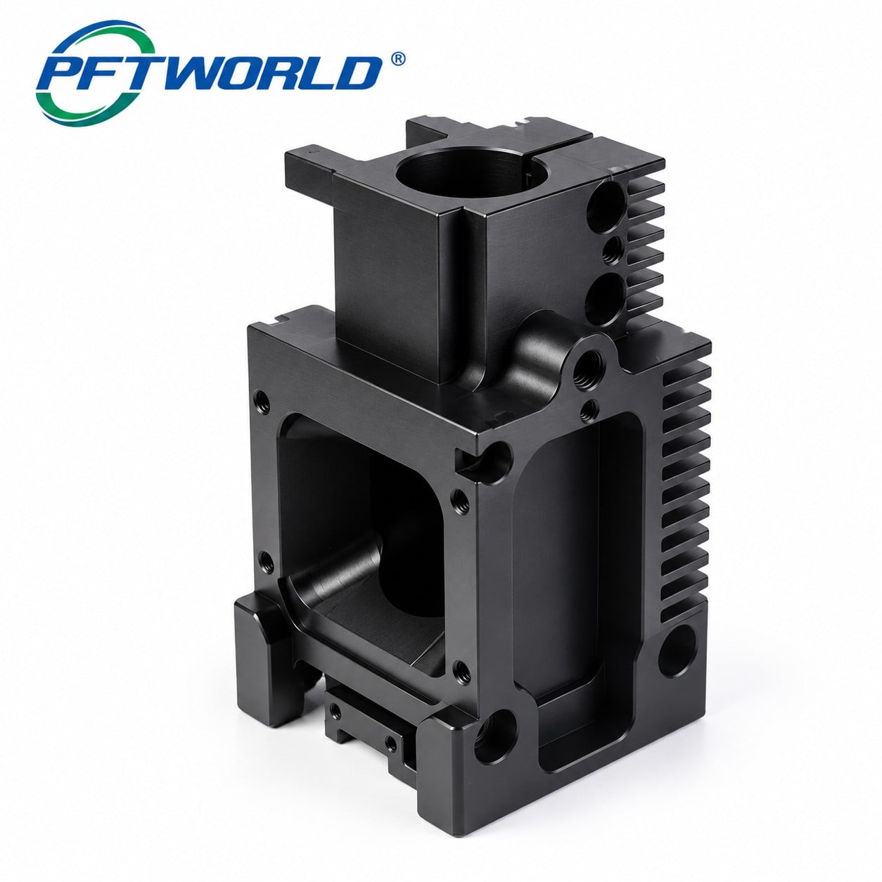
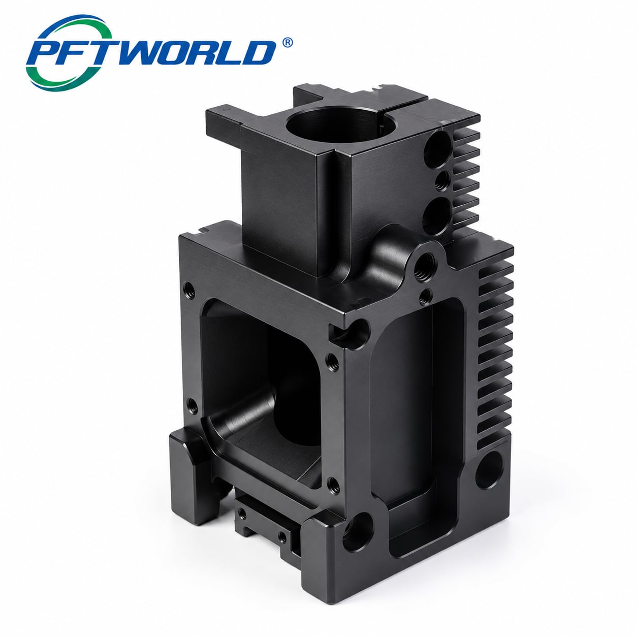
Image reference: a complex housing-like component with multiple openings and mounting features. Its material, surface-treatment process, dimensions, and intended application are not established by the photograph.
Start with the Assembly Interfaces
Direct answer: protect the features that locate, support, or connect mating components; relax other requirements only after checking their function. Record each critical interface together with its dimensional requirement, geometric relationship, finished condition, and inspection evidence.
Ask three questions before refining the drawing:
- What physically locates the housing in the assembly?
- What locates the components inside or against it?
- Which variations would prevent assembly or change performance?
A clearance opening, a locating bore, and a cosmetic recess should not automatically receive the same tolerance. A hole's diameter may control whether a mating part enters, while its axis location and orientation determine where that part sits.
Mark those relationships on the drawing or in an assembly section. Do not expect a supplier to infer a locating feature from its appearance in CAD. Similarly, do not label a feature “noncritical” until its clearance, strength, or other functional requirements have been checked.
Review Tool Access, Support, and Measurement Access Together
Pockets and Internal Corners
Deep cavities and small internal corner radii can restrict tool selection. Conventional end milling leaves a radius at an internal corner; a visually sharp CAD corner does not make that geometry straightforward to cut. Protolabs Network's CNC design guide explains these tool-geometry and access constraints.
Where function permits, consider a larger internal radius, a shallower pocket, or local clearance around a mating corner. Check the mating component before making the change. A larger radius that simplifies machining is not useful if it creates an assembly collision.
Avoid treating a published pocket-depth ratio as a universal acceptance limit. Actual feasibility depends on tool reach, material, workholding, required accuracy, and the surface being cut. Sandvik Coromant's machining application guide identifies vibration and long overhangs as practical process constraints.
Walls, Slots, and Workholding
Large openings and closely spaced slots can leave sections that are difficult to support during machining. Review where the fixture can contact the part without obstructing the cutter or distorting a functional surface.
For a distortion-sensitive housing, ask whether inspection should occur in the free state, under a defined restraint, or in an assembly-representative condition. The drawing and acceptance plan must make that choice explicit rather than allowing different fixtures to produce incomparable results.
Also reserve access for measurement. A feature is not adequately specified merely because a cutter can reach it; the selected probe or gauge must be able to assess the requirement after the relevant manufacturing operations.
Multi-Face Machining and Setup Transfers
Features on several faces may require multiple setups or indexed machining. Where practical, producing related features from a common controlled setup can reduce opportunities for datum-transfer error. It does not eliminate tool, fixture, thermal, or measurement variation.
Ask the supplier to explain how the proposed route preserves the critical relationships. Do not specify five-axis machining simply because the housing looks complex. Three-axis machining with suitable fixtures may be appropriate; indexed or simultaneous multi-axis machining may offer advantages where access and geometry justify it.
PFTWORLD's CNC milling service page provides a relevant starting point for a drawing-based discussion. The actual route still needs project-specific review.
Define Housing Tolerances by Function
Separate Size from Location and Orientation
A bore size requirement does not, by itself, fully define the bore's relationship to the rest of a housing. Review size, form, location, and orientation as distinct functional questions, while accounting for the default rules of the drawing standard.
For example, a mating component may require a particular bore fit and a controlled axis relationship to a mounting face. A cover may need clearance rather than precision location. Applying the same tight dimensional tolerance everywhere can add effort without resolving the actual assembly risk.
Use an explicit datum scheme that represents the functional locating relationships. The designer—not the photograph—must determine which surfaces or features establish that reference system.
ASME Y14.5 provides the standardized language for communicating GD&T requirements. Identify the governing standard and edition on the drawing; have the detailed controls reviewed by someone competent in that system.
Build a Feature-to-Evidence Matrix
The following matrix is a planning aid, not a drawing specification or a universal inspection prescription. Select methods according to access, required uncertainty, and the actual acceptance criteria.
| Interface or feature | Define before quotation | Evidence to discuss |
|---|---|---|
| Locating bore | Size limits, mating condition, required axis relationships, finished state | Suitable bore measurement for size; datum-referenced measurement for location and orientation |
| Mounting face | Functional contact area, form requirements, relation to other interfaces | A measurement plan addressing the specified face and its relationships |
| Threaded attachment | Thread designation, class where applicable, usable depth, finish condition | Appropriate thread gauging and a separately defined depth check |
| Cover or clearance opening | Clearance envelope, corner interference, edge requirements | Dimensional checks; an agreed assembly check where useful |
| Coated mating surface | Treatment specification, masking, final dimensions, inspection stage | Final-state dimensional results and required finish documentation |
For each row, add the drawing characteristic number and identify who approves a proposed change. This makes the table useful during supplier review rather than leaving it as a separate checklist that nobody updates.
Treat Material and Finishing as Design Inputs
A black surface does not identify an alloy or a coating. Select the material from the application's mechanical, environmental, thermal, and manufacturing requirements, then specify the grade and condition needed for the design.
If the material remains undecided, give potential suppliers the relevant operating conditions and request clearly separated alternatives. Do not compare quotations that silently assume different materials, tempers, or treatments. Any substitution needs engineering approval.
If aluminum and anodizing are selected, account for their effect on the finished interfaces. The Aluminum Anodizers Council FAQ explains that anodizing changes dimensions, that the change depends on alloy and process conditions, and that pretreatment can also affect the result.
Consequently, do not prescribe a universal machining allowance from a photograph or a generic coating-thickness value. Agree with the machining supplier and finisher on:
- The treatment specification and required thickness, where applicable.
- Which bores, threads, or contact areas need masking.
- Whether dimensional acceptance applies before or after finishing.
- What inspection is needed after the final operation.
Likewise, distinguish surface texture from appearance. Define functional texture requirements on the relevant surfaces, and define cosmetic acceptance separately. “Smooth black finish” is not a complete requirement for a mating interface.
Specify Evidence That Matches the Requirement
A dimensional report is useful only if it addresses the requirements that matter. Measuring a bore's diameter does not demonstrate its position relative to a mounting face. Passing a thread gauge does not, by itself, document every depth or positional requirement.
A coordinate measuring machine can calculate dimensions, form, and position from measured points. Its results still depend on a suitable inspection program and a verified measurement system, as discussed in Industrial Physics' CMM verification guide.
Before ordering, agree on the datum alignment, accessible measurement areas, part restraint, inspection stage, and characteristics to report. For demanding requirements, ask how the proposed measurement method's uncertainty is considered in acceptance.
A functional assembly check can supplement dimensional evidence, but its limits should be understood. One sample fitting one mating component does not establish interchangeability across the full permitted variation of both parts.
For prototypes, identify which interfaces the build is intended to validate. For repeat production, define the sampling and change-control expectations rather than assuming one accepted first article proves ongoing process stability.
An Illustrative Review: A Bore That Fits but Does Not Align
The following is a hypothetical engineering example, not a PFTWORLD customer case or a specification for the pictured component.
Suppose a housing supports a cylindrical insert, while a mounting face locates the housing against a machine plate. The first drawing controls bore diameter but leaves the bore's relationship to that mounting interface unclear.
The insert may enter the bore, yet the assembly can still be misaligned. Tightening the diameter tolerance alone would not necessarily address that problem.
The review should first identify how the housing and insert are located in service. The designer can then establish the appropriate datum references and geometric controls, check the mating-part tolerance stack, and define the final inspection condition.
Next, the supplier evaluates whether the fixture and machining sequence can maintain those relationships. If finishing affects the bore, its final-state acceptance is addressed in the same review. Inspection then checks both the fit-related size and the specified relationship—not just the easiest diameter to measure.
Make Housing Quotations Comparable
The most useful cost discussion starts with avoidable requirements: inaccessible corners, unnecessary pocket depth, redundant precision callouts, unclear finishing, or inspection documents requested only after the order is placed.
Do not ask every supplier merely to “quote the model.” Send the same released package and ask each supplier to list assumptions, exceptions, and proposed design changes. Separate one-time programming or fixture charges from recurring part costs where applicable.
A practical housing RFQ should include:
- Revision-controlled geometry: the model and drawing, units, part number, and matching revision.
- Material definition: grade, condition, and any restrictions on substitutions.
- Functional interfaces: mating information, datums, critical characteristics, and fit requirements.
- Feature details: threads, usable depths, sections through hidden geometry, and edge requirements.
- Finishing: treatment, texture and appearance requirements, masking, and final acceptance state.
- Inspection: characteristic list, report format, required material or finish records, and approval points.
- Commercial scope: quantities by release, prototype objectives, delivery location, requested schedule, packaging, and quotation exclusions.
Protolabs Network's technical drawing guide explains why threads, tolerances, and surface requirements need explicit communication alongside geometry. Agree on document precedence with your supplier rather than assuming every manufacturer resolves drawing/model conflicts identically.
When reviewing suppliers for custom CNC machined parts, look for a response that addresses your critical interfaces, not just a generic statement about precision.
Frequently Asked Questions
Does a CNC Housing Need the Tightest Available Tolerances?
No. Allocate tolerances from assembly and performance requirements, including mating-part variation. Tighten a requirement because function needs it, not because the part looks complex. A tight size tolerance cannot replace a missing geometric relationship.
Should Housing Bores Be Inspected After Anodizing?
If the drawing requires the finished bore to meet the fit limits and anodizing affects that surface, the inspection plan must address the post-anodizing condition. Masking or intermediate checks may be appropriate, but neither should leave final acceptance ambiguous.
Is Five-Axis Machining Always Better for a Complex Housing?
No. Evaluate access, setup transfers, workholding, tolerances, quantity, and cost together. More axes can help particular geometries, but they do not remove all reach, rigidity, or inspection constraints.
Can a Supplier Quote from a Photograph Alone?
A photograph can support an initial discussion, but it does not establish dimensions, internal geometry, material, or acceptance requirements. A production quotation needs enough controlled technical information to define what will actually be supplied.
Prepare the Interfaces Before Requesting a Quote
Before releasing the RFQ, complete the feature-to-evidence matrix and resolve any difference between the modeled geometry and the intended assembly. That gives engineering, procurement, machining, and inspection teams a common basis for the order.
Have a housing design ready for review? Share your revision-matched 2D drawing and 3D CAD model with PFTWORLD, together with the critical mating interfaces, material requirements, finish condition, and quantities. Contact PFTWORLD about your housing RFQ to discuss manufacturability, specifications, and quotation requirements.
Table of Contents
- Start with the Assembly Interfaces
- Review Tool Access, Support, and Measurement Access Together
- Define Housing Tolerances by Function
- Treat Material and Finishing as Design Inputs
- Specify Evidence That Matches the Requirement
- An Illustrative Review: A Bore That Fits but Does Not Align
- Make Housing Quotations Comparable
- Frequently Asked Questions
- Prepare the Interfaces Before Requesting a Quote