 EN


Engineering guide | Custom CNC machined parts
CNC Machined Parts Design Guide: Threads, Holes, and RFQ Essentials
A practical guide for engineers and OEM buyers who need clearer DFM decisions, more comparable quotations, and fewer assembly surprises.
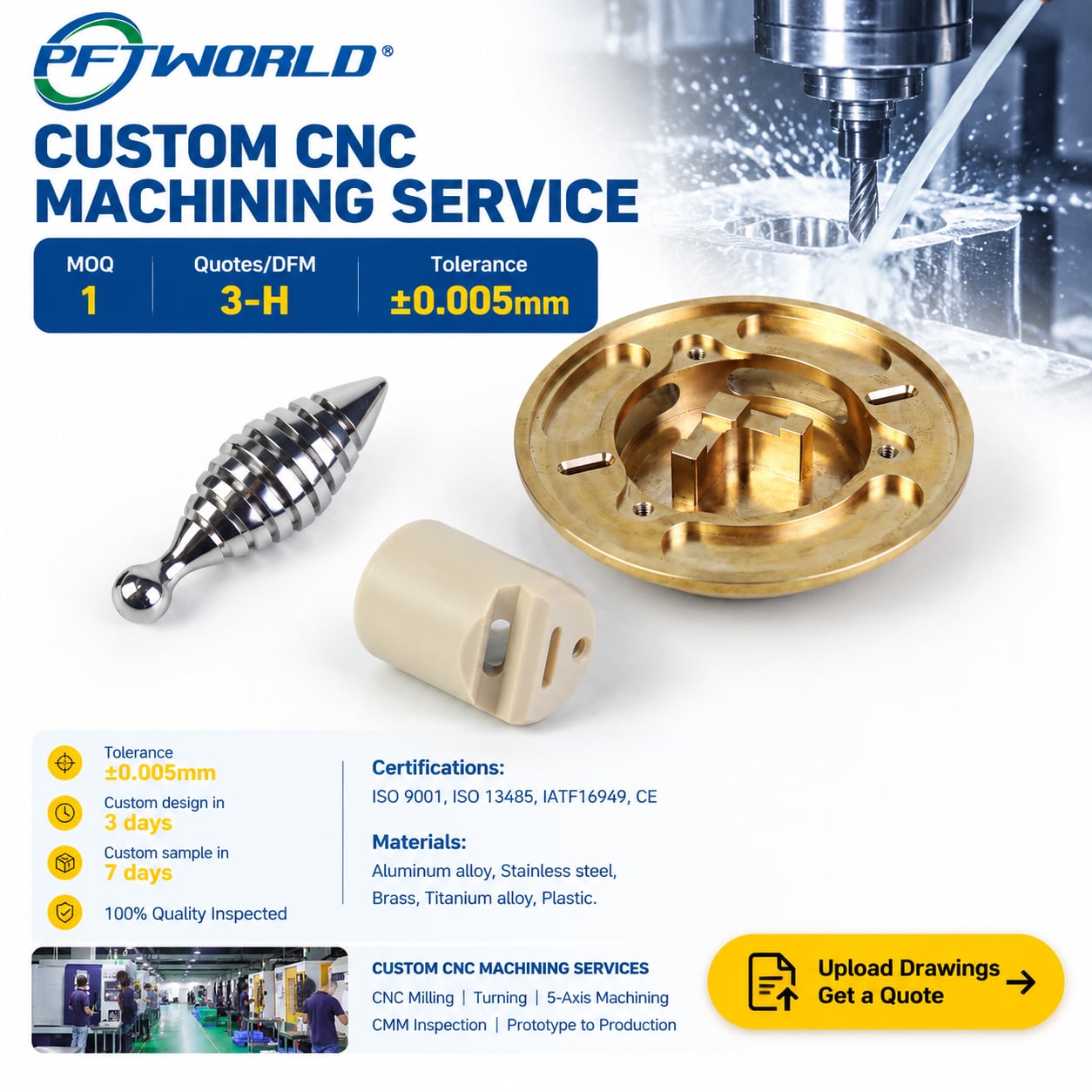
When a custom CNC part includes threads, holes, bosses, flanges, wrench flats, or milled tabs, the geometry is only one part of the manufacturing decision. The way those features are defined can affect tool access, workholding, setup count, inspection, assembly, cost, and quotation accuracy. The examples shown here represent visible feature types only; their exact materials, dimensions, tolerances, and applications have not been confirmed from the photographs.
What Should Be Reviewed Before Requesting a CNC Quote?
Before sending a model to a CNC machining supplier, review feature function, tool access, process sequence, tolerance priority, and inspection evidence. Ask what each hole, thread, boss, shoulder, or flat does; whether the tool can reach it rigidly; whether turning, milling, repositioning, or secondary operations are required; which dimensions affect fit; and what must be measured.
This review is more useful than applying a tight tolerance to every dimension. Tight tolerances can increase machining and inspection effort, while unclear functional requirements can still leave the supplier unable to select the right process.
1. Start With the Function of Each Feature
Holes: clearance, locating, flow, or fastening?
A hole may be used for a clearance fastener, a locating pin, a bearing, a shaft, a fluid passage, or a threaded connection. These functions require different design and inspection approaches.
A through hole is often simpler to machine than a blind hole because chips and coolant have a path through the part. A blind hole may be necessary when the opposite surface must remain intact, but its depth, tool access, and chip evacuation should be reviewed early.
If a hole locates a dowel, bearing, bushing, or shaft, diameter alone may not be enough. The drawing may also need to control position, perpendicularity, cylindricity, or the relationship to a datum. If the hole only provides clearance for a fastener, an unnecessarily tight diameter tolerance may add cost without improving the assembly.
Threads: define the connection, not only the pitch
For external or internal threads, an RFQ should identify the thread standard and designation, major diameter and pitch where relevant, thread class or fit, usable engagement length, internal or external form, mating component, inspection method, and any lead-in chamfer, relief, or runout requirement.
A blind threaded hole normally needs additional unthreaded depth below the usable thread. That space allows the tool to finish the thread and provides room for chips. Specifying more thread depth than the joint needs can increase cycle time and complicate inspection without improving the connection.
2. Check Tool Access, Depth, and Internal Corners
CNC machining is a subtractive process. The tool must physically reach the material, remove chips, and remain rigid enough to maintain the required geometry and finish.
Deep holes and narrow features
As hole depth increases relative to diameter, chip removal and tool deflection become more difficult. A blind hole inside a deep pocket or close to a tall wall may require a longer tool, a different sequence, or an additional setup. These choices can affect accuracy and price.
During design review, ask whether a through hole could replace a blind hole, whether the specified depth is necessary, whether there is a clear approach for the drill, end mill, reamer, or thread tool, whether a standard tool size is suitable, and whether the feature is too close to an edge or tall wall.
Internal radii and external edge breaks
Milling cutters are round, so internal corners normally receive a radius rather than a perfectly sharp corner. If a sharp internal corner is functionally necessary, the part may require a special tool, slower machining, or a secondary process, depending on the geometry.
External edges are often easier to manufacture with a chamfer or a defined edge break. If the exact chamfer size is not functionally important, avoid tightly controlling it. Instead, state the required edge condition, such as “break sharp edges” or “remove burrs,” and identify any edge that must remain sharp.
3. Treat Bosses, Flanges, and Mounting Patterns as Assembly Features
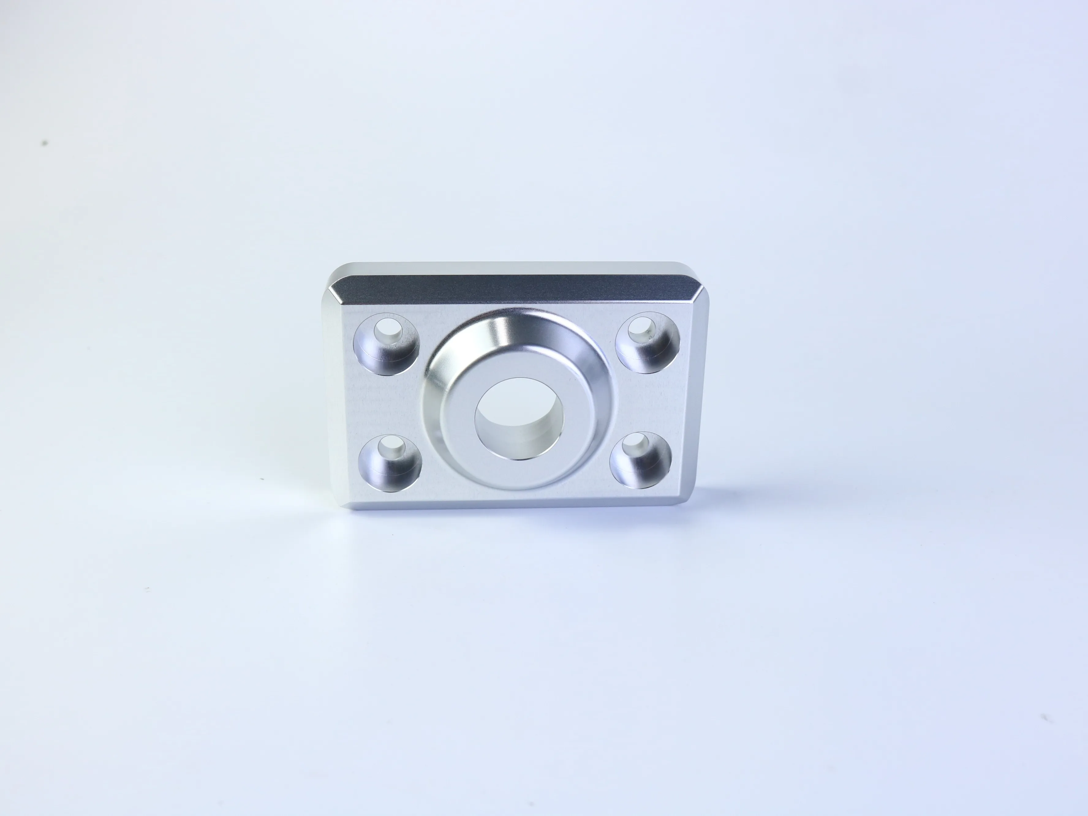
A rectangular component with a central circular feature and a four-hole mounting pattern might be used as a mounting plate, flange, adapter, or bracket, but a photograph does not confirm the application. For this type of part, the most important questions are usually relational:
- Is the central bore concentric with the boss or outer feature?
- Is the hole pattern symmetric around a datum axis?
- Must the mounting face be flat enough to seal or locate another part?
- Is the boss height controlled because it determines axial position?
- Are the bolt holes clearance holes, tapped holes, counterbores, or countersinks?
- Is there a required relationship between the hole pattern and the central feature?
A set of separate linear dimensions may not communicate these relationships effectively. Where the assembly depends on feature location or orientation, use a clear datum structure and appropriate GD&T callouts. The supplier also needs to know which surfaces are primary references during setup and inspection.
4. Apply Tolerances by Function
A practical tolerance strategy separates general dimensions, functional dimensions, and geometric relationships. General tolerances can suit non-critical lengths, cosmetic steps, or clearance features when the drawing standard is clear. Functional dimensional tolerances belong next to fits, shoulders, hole diameters, thread interfaces, and locating features. Geometric tolerances are appropriate for position, flatness, perpendicularity, profile, or orientation relationships that affect assembly.
- General tolerance: Use for non-critical features under a defined drawing standard.
- Functional dimensional tolerance: Use where size directly affects fit or performance.
- Geometric tolerance: Use datums and GD&T where feature-to-feature relationships matter.
Do not copy a supplier’s standard tolerance into your drawing without checking whether it matches your design intent. A quoted standard is not automatically suitable for a bearing seat, sealing face, threaded connection, or precision locating feature. Also separate manufacturing tolerance from surface finish. A part can meet a size requirement and still fail if a sealing or sliding surface has the wrong roughness or tool-mark direction.
5. Specify Material and Surface Treatment Separately
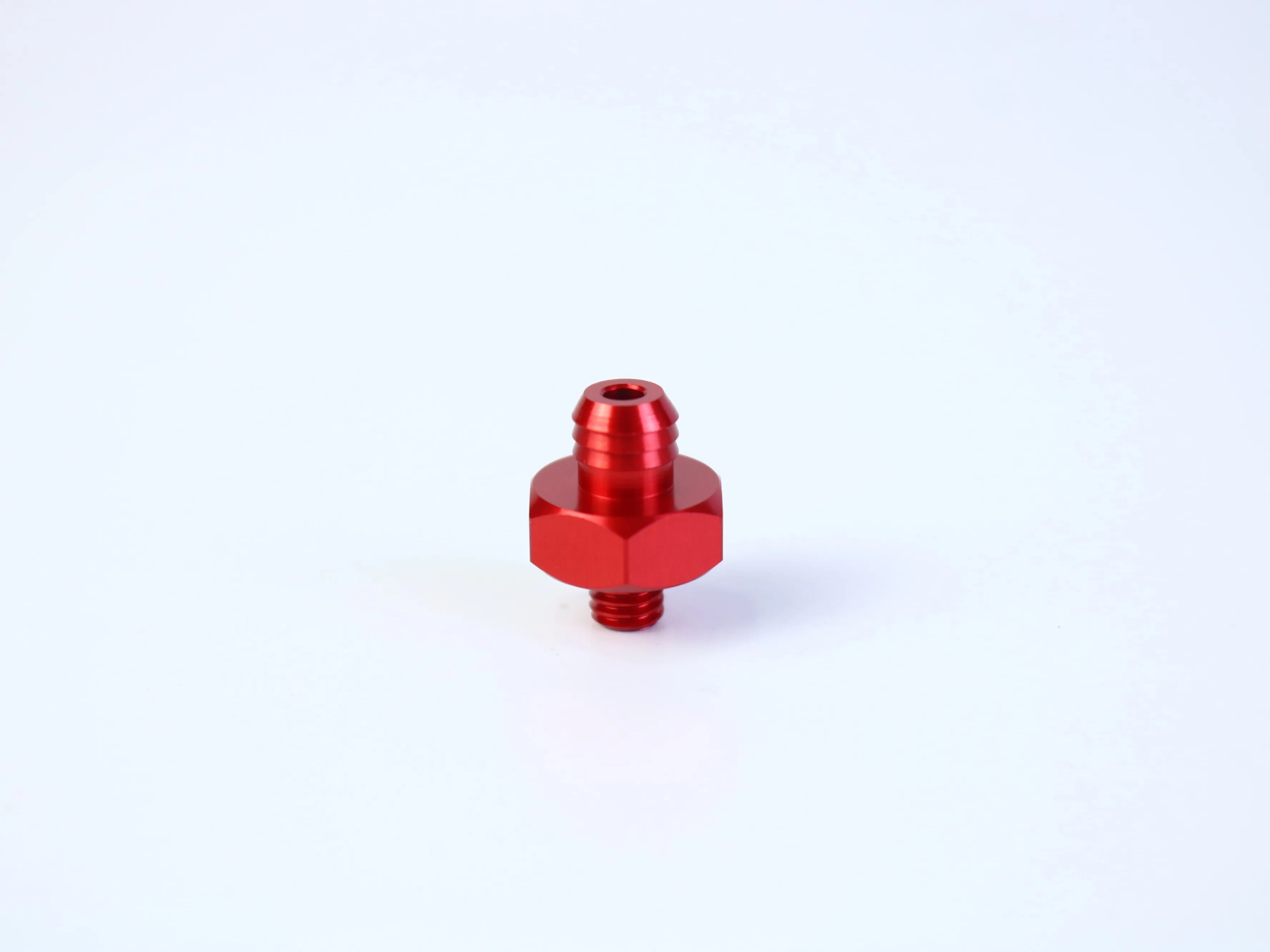
The color or reflectivity of a photographed component does not prove its material. A silver part might be aluminum, stainless steel, plated steel, or another alloy; a red part might be anodized, painted, plated, or photographed under colored lighting.
The RFQ should state the material grade and condition where relevant, together with any required certification. If the material is not yet fixed, explain the performance requirements instead: strength, weight, corrosion exposure, conductivity, wear, magnetic behavior, temperature, and compatibility with mating materials.
Surface treatment should also be specified separately. Anodizing, passivation, plating, blasting, polishing, and powder coating can affect appearance, corrosion resistance, wear, conductivity, dimensions, and masking. Critical dimensions may need evaluation before and after finishing. A useful RFQ identifies functional or visual surfaces, the required finish standard, and whether threads, bores, datums, or sealing surfaces must be protected.
6. Make the RFQ Complete Enough to Compare Suppliers
A supplier cannot produce a comparable quotation if each bidder has to guess a different set of assumptions. Include the following information whenever it is available.
- Design data: revision-controlled 2D drawing, 3D CAD model, units, projection method, material, surface treatment, masking, general tolerances, critical tolerances, datums, GD&T, thread standards, depths, mating information, deburring, and edge conditions.
- Commercial data: prototype, pilot, small-batch, or production stage; required quantity; expected annual volume if known; sample quantity; delivery milestone; packaging, labeling, traceability, destination, trade terms, and required quality documents.
- Technical questions: Which features create the greatest manufacturability risk? Which dimensions are assumed to use a general tolerance? Does the process require multiple setups or secondary operations? Are tooling, fixtures, finishing, inspection, and packaging included?
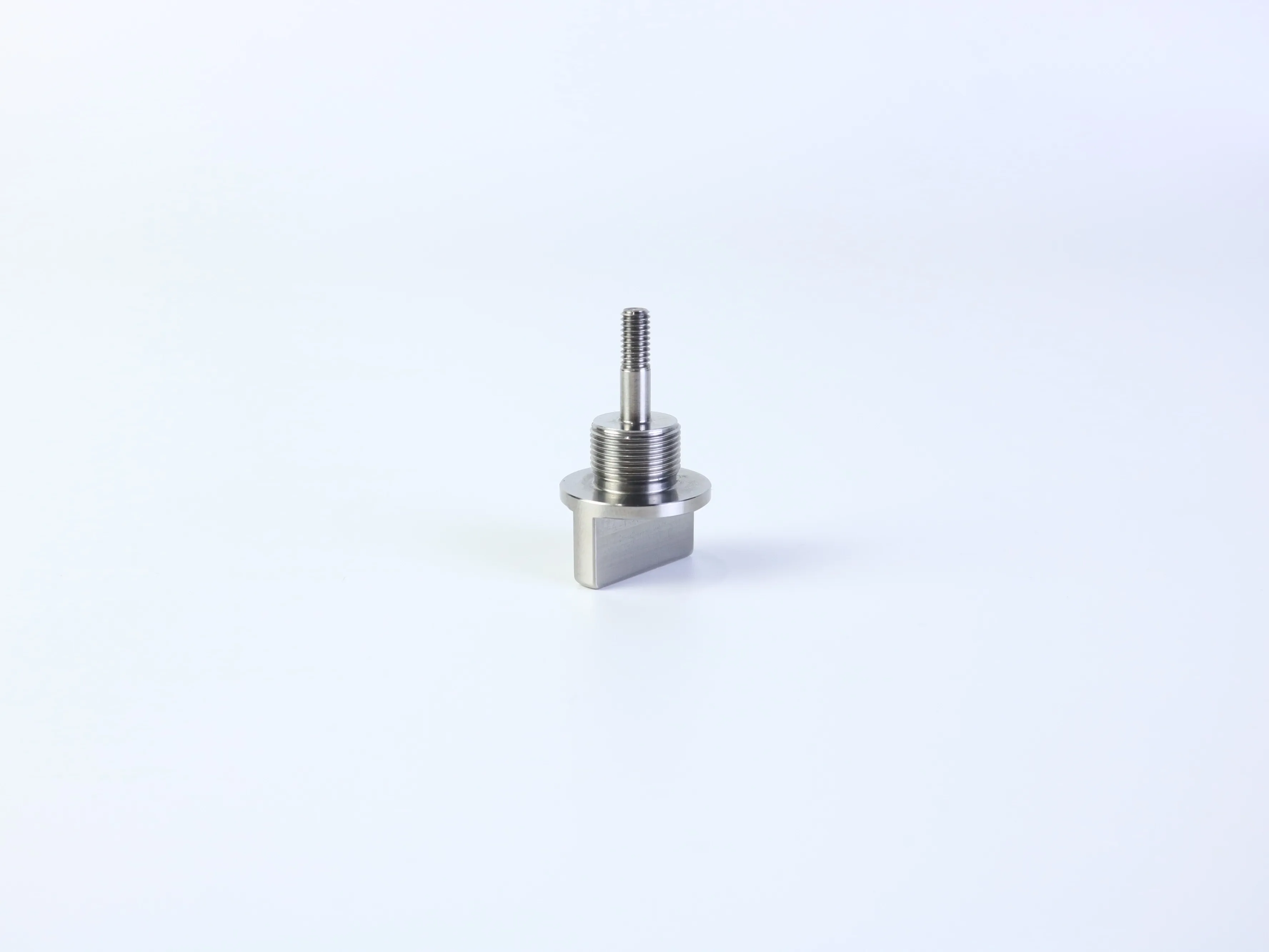
For a turned-and-milled component, identify the critical axis-to-flat relationship and rotational orientation. A simple turning operation may not be enough when the part includes a flange, threaded section, stem, rectangular tab, milled flat, or cross-feature. The drawing should make the relationship measurable rather than visual.
A better RFQ question
Ask the supplier to list manufacturability risks and quotation assumptions before production. This makes hidden secondary operations, unclear threads, missing inspection evidence, and ambiguous tolerances visible while changes are still manageable.
7. Common Cost and Quality Risks
Unnecessary precision
Applying a tight tolerance to every feature can increase machining time, inspection effort, scrap risk, and supplier selection constraints. Reserve precision requirements for features that need them.
Hidden secondary operations
A turned body with a milled flat, slot, cross-hole, or rectangular tab may need another setup. If the drawing does not identify the relationship between the turned axis and the milled feature, clarification may be needed before quoting or production.
Unclear threads and poor inspection planning
A thread callout without a standard, class, effective length, or mating requirement is incomplete. If a hole pattern, flange face, boss, or threaded axis is functionally important, state how it should be referenced and verified. “Inspect all dimensions” is less useful than identifying critical characteristics and the required report format.
8. Practical CNC DFM and RFQ Checklist
- Every hole has a defined function, and every blind-hole depth is necessary and accessible.
- Thread standards, classes, depths, mating parts, reliefs, and inspection methods are identified.
- Hole patterns are tied to clear datums when location matters.
- Internal corners allow a realistic cutter radius, and thin walls or deep pockets have been reviewed for rigidity.
- Turning and milling features have a clear process and orientation.
- Critical dimensions are separated from general dimensions.
- Material, condition, finish, masking, burr, edge-break, and cosmetic requirements are clear.
- Quantity, production stage, delivery expectation, and inspection documents are stated.
- The supplier is asked to identify assumptions before production.
FAQ: CNC Machined Parts, Threads, and RFQs
Can a 3D CAD model alone be used for a CNC quotation?
Sometimes, but it may not communicate materials, tolerances, threads, surface finish, datums, inspection requirements, or features that are not fully represented by model geometry. A revision-controlled drawing or written specification reduces assumptions.
Are through holes always better than blind holes?
No. Through holes are often simpler when they do not interfere with the assembly, but a blind hole may be necessary to protect a surface or meet a functional requirement. Choose the simplest feature that satisfies the design.
How should I specify a threaded CNC part?
Identify the thread standard, size, pitch, class or fit, usable length, internal or external form, relief or chamfer requirements, mating component, and inspection method. A visual thread is not sufficient evidence of compatibility.
Should every CNC dimension have a tight tolerance?
No. Tight tolerances should be linked to fit, function, or performance. A clearly defined general tolerance can be appropriate for non-critical features.
Prepare a More Comparable CNC Machining RFQ
Threaded fittings, mounting plates, bosses, flanges, and turned-and-milled components can all be manufactured successfully when their functional requirements are translated into accessible geometry, appropriate tolerances, clear process assumptions, and measurable inspection criteria.
The goal is not to make every feature more complex or more precise. The goal is to give the supplier enough information to select a suitable process, identify risks early, quote the same scope you intended, and verify the features that matter to your assembly.
Discuss Your Custom CNC Project
For a manufacturability and quotation discussion, prepare the latest 2D drawing, 3D CAD model, material and finish requirements, quantity, production stage, and inspection expectations. PFTWORLD’s public CNC machining information can be reviewed before submitting your project details.
Review Custom CNC Machining Services