 EN


CNC Machining RFQ Checklist: How to Prepare Complex Parts for DFM Review
A practical guide for engineers and procurement teams preparing complex CNC machined parts for quotation, manufacturability review, inspection, and production planning.
When a machined component has multiple faces, threaded features, deep pockets, slots, or helical geometry, the quality of the quotation depends on more than the CAD model. A supplier must understand how the part will be held, reached by cutting tools, inspected, finished, and assembled.
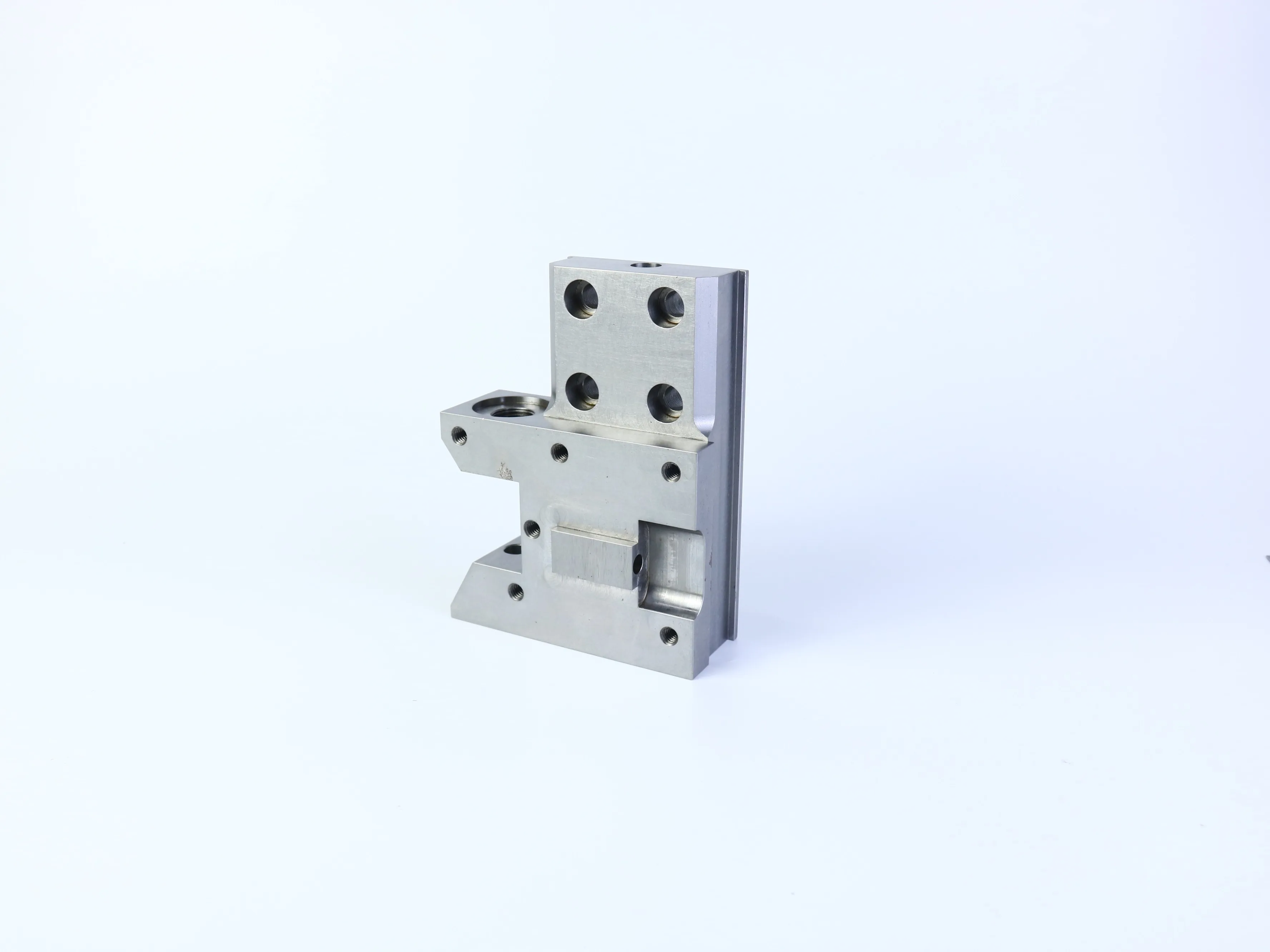
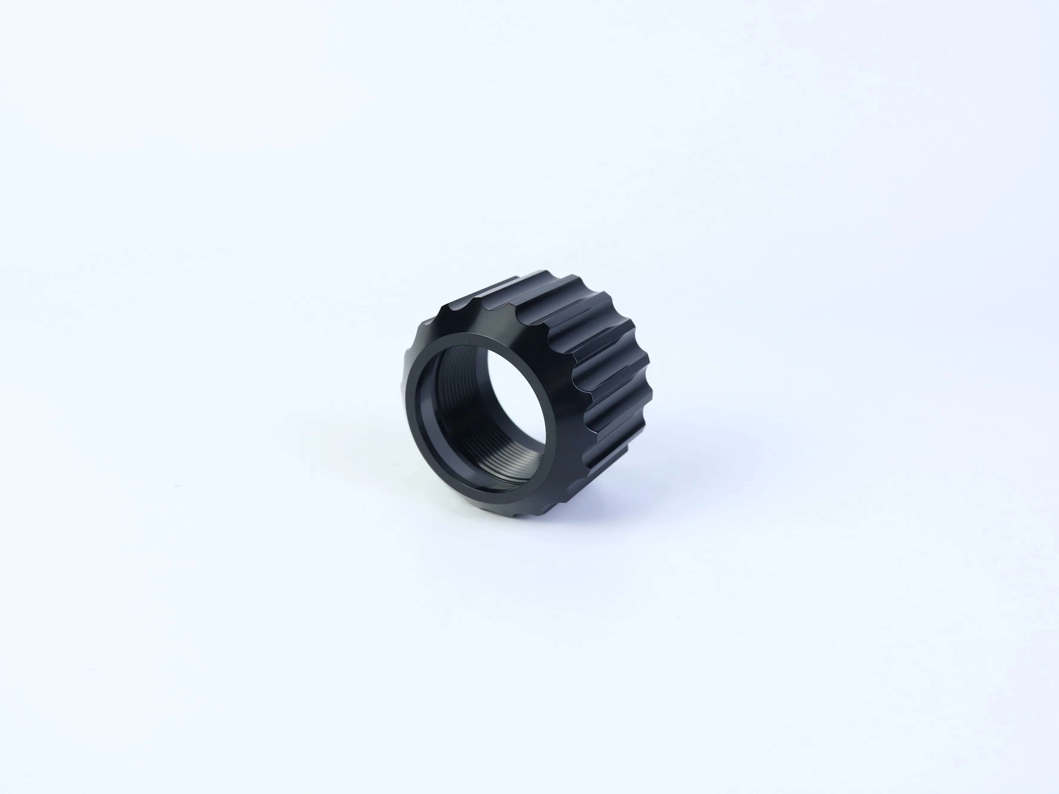
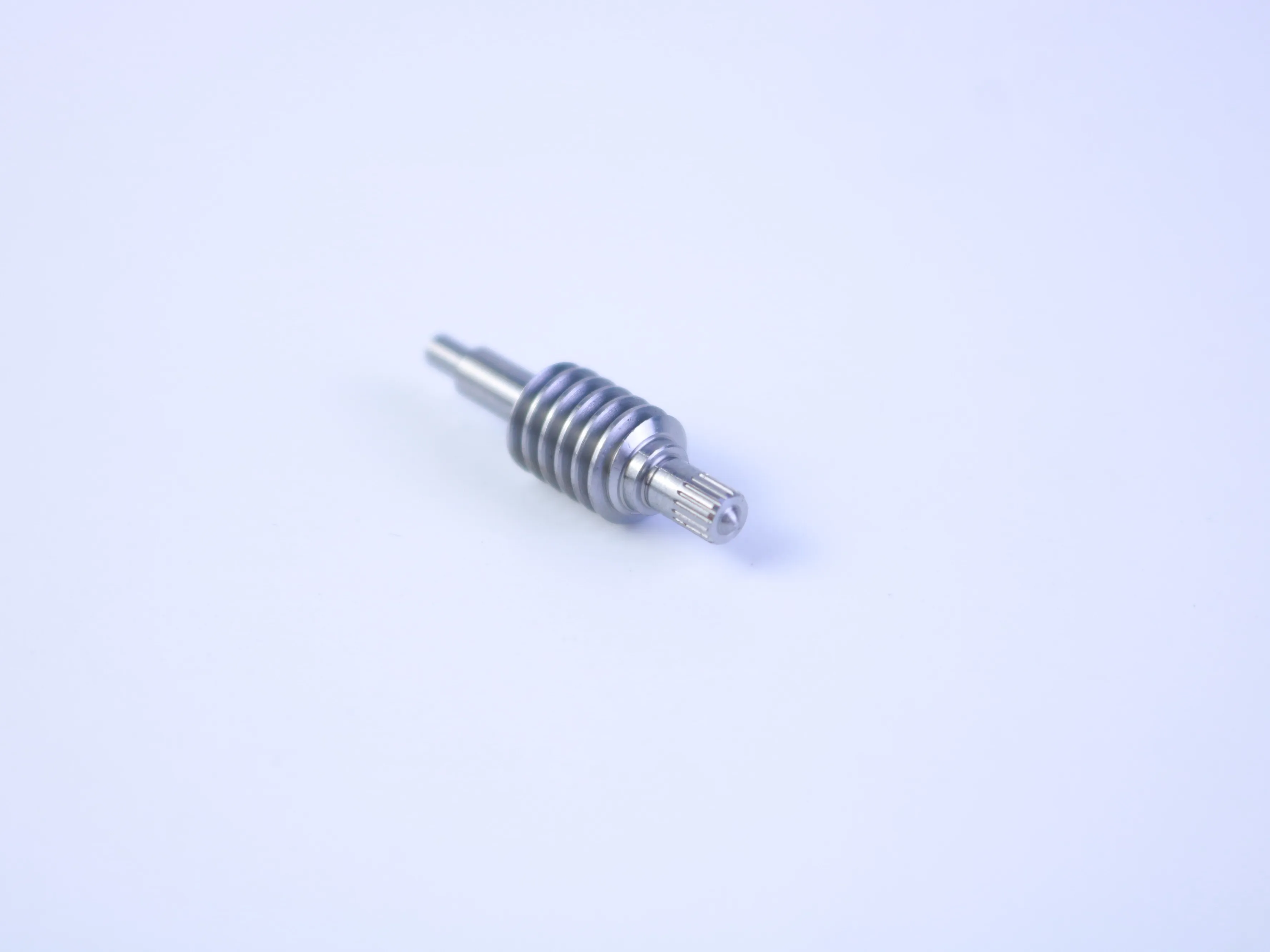
The three component types shown below illustrate the challenge: a multi-feature milled bracket, a grooved threaded cylindrical component, and a worm-shaft-like transmission part. Their exact materials, dimensions, tolerances, and applications are not confirmed from images alone. However, they show why a complete CNC machining RFQ checklist and an early DFM review can prevent avoidable cost and production risk.
The short answer: what makes a complex CNC RFQ accurate?
A useful RFQ should connect four things:
- The geometry: a current 3D CAD model and a controlled 2D drawing.
- The functional requirements: critical fits, datums, threads, sealing faces, alignment features, and mating parts.
- The production scope: material, quantity, finishing, inspection, packaging, destination, and delivery expectations.
- The open decisions: any assumption that still needs supplier feedback or engineering approval.
A model may show the shape of a component, but it usually does not communicate every requirement needed to produce and inspect it consistently. A DFM review closes that gap before the quotation becomes a purchase commitment.
Why complex geometry changes the quotation
CNC machining is governed by physical constraints. Cutting tools have real diameters, lengths, corner radii, and stiffness limits. Fixtures must hold the workpiece securely, while the machine must reach each surface without excessive vibration, deflection, heat, or chip accumulation.
A complex milled bracket may require several orientations to machine holes and mounting faces. A threaded ring may need turning, internal threading, grooving, deburring, and controlled inspection of the mating thread. A worm-shaft-like part may involve turning, helical or gear-form machining, secondary milling, and verification of the functional tooth or spline geometry.
The most important cost drivers are often not raw material alone. They can include:
- Number of setups and re-clamping operations
- Special or long-reach cutting tools
- Small tools required for narrow slots or internal corners
- Additional finishing passes
- Workholding and datum-transfer requirements
- Thread gauges, optical measurement, or other inspection needs
- Secondary operations and surface treatment
- Rework risk when several critical features are controlled from different setups
This is why two parts with similar size or material volume can receive very different quotations.

A practical DFM review for complex CNC machined parts
1. Check tool access before discussing tolerances
The first question is not only “Can the machine make this shape?” It is “Can a suitable tool reach the shape while remaining stable?”
Deep pockets, narrow slots, tall walls, and sharp internal corners can force a supplier to use smaller or longer tools. That may increase cycle time and make the process more sensitive to chatter, tool wear, and deflection. Where a feature is not functionally required, a more accessible geometry may produce a more stable process.
For internal corners, remember that a standard milling tool is round. A perfectly sharp internal 90-degree corner normally requires a secondary process or a design change. Adding a practical internal radius can allow a larger and more rigid tool to be used, although the suitable radius depends on the feature, tool, material, and functional requirement.
2. Identify the datums and the most important setup
A drawing should identify which surfaces establish the part coordinate system and which features control assembly. This matters particularly for brackets with perpendicular faces, repeated hole patterns, and recessed mounting areas.
Ask the supplier to explain which surface will be used as the primary datum, how the part will be supported during each operation, which features can be completed in one setup, where re-clamping may introduce alignment risk, and how the critical relationship will be inspected.
If the functional hole pattern, bearing bore, or mounting face is not clearly prioritized, the supplier may quote a technically possible process that does not reflect the real assembly requirement.
3. Define threads, fits, and mating requirements
A threaded cylindrical component should not be specified only as “internal thread” or “standard thread.” The RFQ should state the thread standard, nominal size, pitch, class or tolerance where applicable, effective depth, relief requirements, and the mating component.
The same principle applies to holes, bores, shafts, and splines. A nominal diameter alone does not tell the manufacturer whether the feature is a clearance hole, a slip fit, a press fit, a sealing bore, or a locating feature.
For a worm-shaft-like component, the RFQ may also need to identify the gear or worm standard, lead or pitch information, tooth form, hand, mating wheel, functional backlash requirement, and inspection method. These parameters cannot be inferred reliably from a photograph.
4. Separate functional tolerances from cosmetic or non-critical dimensions
Applying very tight tolerances to every dimension can increase machining and inspection effort without improving product performance. Identify the dimensions that control assembly fit, alignment, sealing, rotation or transmission, load transfer, interchangeability, or surface contact.
Use general tolerances for non-critical features where appropriate, and apply tighter requirements only where engineering analysis supports them. A supplier should be able to explain how each critical tolerance will be produced and verified. Do not specify a universal tolerance or surface-finish value without considering material, part size, geometry, process route, temperature, finishing, and inspection equipment.
What to include in a CNC machining RFQ checklist
The following information is suitable for most complex prototype and production machining projects. Not every project needs every item; the goal is completeness where a requirement affects function, cost, quality, or delivery.
How to compare CNC machining quotes fairly
A low unit price is not automatically the lowest total cost. Before comparing suppliers, confirm that each quotation covers the same scope.
- Same drawing revision and CAD model
- Same material grade and condition
- Same quantity and price-break structure
- Same tolerances, threads, and finishing requirements
- Same inspection records and certificates
- Same packaging and shipping assumptions
- Same tooling, setup, and secondary-operation scope
- Same lead-time definition and delivery terms
- Clear list of exclusions, alternatives, and open questions
Ask each supplier to identify assumptions instead of silently filling gaps. If the material is specified but the surface treatment is undecided, request the base-machined price and list the finishing option separately. This makes quotations easier to compare and gives the engineering team a clear decision point.
Common RFQ mistakes that create avoidable risk
Sending only an image or screenshot
A product image is useful for communication, but it cannot replace a controlled CAD model and drawing. It does not define scale, tolerances, thread standards, material, or inspection requirements.
Sending a model without a drawing
The model may show the nominal shape but omit datums, general tolerances, surface roughness, thread callouts, masking zones, or acceptance documentation.
Applying tight tolerances everywhere
Over-specification can make the quote unnecessarily expensive and obscure which features are genuinely important. Mark the critical features and explain their function.
Leaving finishing requirements until after machining
Anodizing, plating, heat treatment, grinding, polishing, and other operations can affect dimensions, appearance, corrosion performance, and inspection. Define them before the quote is finalized.
Comparing prices with different assumptions
One supplier may include inspection and deburring while another may exclude them. One quotation may assume a standard material or relaxed tolerance. Confirm scope before interpreting the price difference.
Omitting production stage information
A prototype, a small validation batch, and recurring production may require different fixture, inspection, packaging, and process-planning decisions. State the immediate quantity and expected production path when known.
A better supplier discussion: ask for the process logic
A capable CNC machining supplier should be able to discuss more than machine availability. During the engineering review, ask:
- Which features create the greatest tool-access or workholding risk?
- Can the part be completed with fewer setups without compromising functional datums?
- Which tolerances are likely to affect cycle time or inspection cost?
- How will threads, bores, holes, slots, and tooth-like features be verified?
- Do finishing operations change any critical dimensions?
- What information is still missing before the quotation can be considered firm?
- Which design alternatives would reduce risk without changing the intended function?
The purpose is not to ask a supplier to redesign the part without authorization. It is to create a transparent engineering conversation before cost and schedule are fixed.
Frequently asked questions
What is the most important item in a CNC machining RFQ?
There is no single item for every project. A current drawing and CAD model provide the geometry, but the most important information is usually the combination of functional requirements, material, quantity, tolerances, finishing, inspection, and delivery scope.
Can a supplier quote a complex part from a photo?
A photo can support an early feasibility discussion, but it is not enough for a controlled production quotation. A proper quote normally requires a current CAD model, a 2D drawing, and the commercial and quality requirements that define acceptance.
Should I provide both a 2D drawing and a 3D CAD model?
Yes, when available. The 3D model communicates the nominal form, while the 2D drawing normally controls dimensions, tolerances, datums, threads, surface notes, revision, and inspection requirements.
How do internal corners affect CNC machining cost?
Sharp or deep internal corners may require smaller, longer, or special tools and may increase setup or finishing effort. If the radius is not functionally constrained, a more accessible radius may support a more stable process. The suitable value must be confirmed against the part’s function and manufacturing route.
What should I do if the material or finish is not finalized?
Mark it as an open engineering decision. Ask suppliers to quote the currently preferred option and list approved alternatives separately. Do not allow an unapproved substitute to become an invisible assumption in the quotation.
Conclusion: treat the RFQ as an engineering document
Complex CNC machined parts are easier to quote, manufacture, inspect, and scale when the RFQ communicates both geometry and function. For brackets, threaded cylindrical components, worm-shaft-like parts, and other multi-feature designs, the early review should focus on tool access, setup strategy, datums, threads, critical tolerances, finishing, and inspection.
A complete RFQ does not need unnecessary specifications. It needs the right specifications clearly connected to the part’s intended use. That is what allows an engineering team and a CNC machining supplier to identify risk before it becomes rework, delay, or an unexpected charge.
Have a complex CNC machined component to manufacture? Share the current 2D drawing, 3D CAD file, required quantity, material, finishing requirements, and critical functional features with PFTWORLD for a discussion of manufacturability and quotation scope. Request a CNC machining quote through your verified PFTWORLD contact page.
Table of Contents
- The short answer: what makes a complex CNC RFQ accurate?
- Why complex geometry changes the quotation
- A practical DFM review for complex CNC machined parts
- What to include in a CNC machining RFQ checklist
- How to compare CNC machining quotes fairly
- Common RFQ mistakes that create avoidable risk
- A better supplier discussion: ask for the process logic
- Frequently asked questions
- Conclusion: treat the RFQ as an engineering document