 EN


CNC Machining Design Guide
How to Design CNC Machined Mounting Brackets for Better Fit and Lower Cost
A practical guide for engineers and procurement teams reviewing bracket geometry, tolerances, machining access, inspection requirements, and supplier quotations.
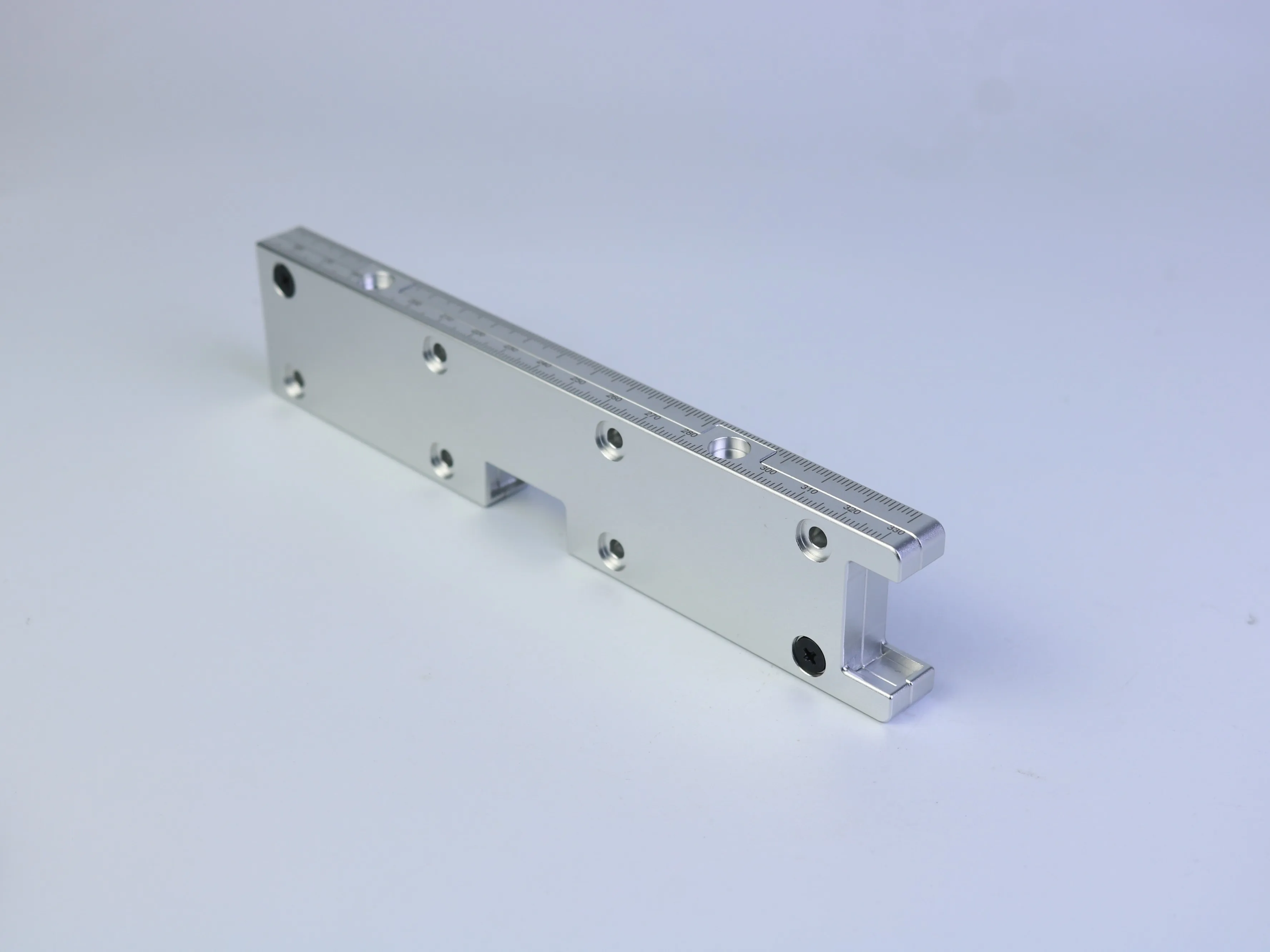
A CNC machined mounting bracket may look like a straightforward metal support: a long body, several mounting holes, a few steps, and perhaps an opening for clearance. In production, however, small decisions in the bracket design can affect alignment, workholding, machining time, inspection effort, and assembly performance.
The key question is not simply whether a supplier can machine the bracket. It is whether the part can be defined clearly enough to produce repeatably and inspected against the way it will function in the assembly.
This guide explains how engineers and procurement teams can review a custom CNC machined mounting bracket before requesting quotations. The examples are based on visible component geometry, but no material, dimension, tolerance, application, or production history is assumed.
1. Define the bracket by its assembly function
Before selecting a material or specifying a machining tolerance, identify what the bracket must do in the assembly. Ask four questions:
- Which surface locates the bracket?
- Which holes fasten it, and which holes locate another component?
- Which faces must remain perpendicular, parallel, or flush?
- Which openings provide clearance rather than structural support?
These questions help separate critical features from non-critical ones. A mounting hole used only for a loose fastener may not need the same positional control as a hole that receives a locating pin. Similarly, a visible outer face may be cosmetic, while an internal shoulder may control the position of a mating part.
A useful drawing should express those relationships through a consistent datum scheme. GD&T is commonly used to communicate functional relationships between features; ASME identifies Y14.5 as an authoritative guideline for the language of geometric dimensioning and tolerancing. The correct scheme depends on the design, but the principle is general: tolerance the part according to how it assembles, not according to what is easiest to dimension on a screen.
2. Review the geometry for CNC tool access
The pictured bracket includes a long body, stepped regions, multiple holes, and recessed or open areas. Features like these are well suited to CNC milling in principle, but their manufacturability depends on the relationship between feature depth, width, corner radius, and tool access.
Internal corners and pockets
A standard milling cutter is round, so an internal corner normally receives a radius rather than a perfectly sharp corner. If a mating part requires a sharp internal corner, the design may need a relief, a different tool strategy, or a secondary process. A larger, consistent radius can often simplify machining while preserving the required clearance.
Deep slots and narrow walls
Slots, recesses, and open sections can create long tool reach, limited chip evacuation, vibration, or local distortion. Review whether the feature is deep because of a real functional need and whether a wider radius, shallower pocket, or redesigned support could deliver the same result.
Holes, counterbores, and threads
For every hole, identify its purpose. Specify whether it is a clearance hole, tapped hole, counterbore, countersink, reamed hole, or locating feature. Include the applicable thread standard and fit where relevant.
Workholding and access
Ask whether the tool can approach each feature without colliding with adjacent walls and whether the workpiece can be supported during cutting. The final answer depends on material, part size, quantity, machine configuration, and required finish.
Hole position should be related to the functional datums. A pattern that looks evenly spaced in a photograph may still require careful control relative to an edge, step, or mating face. If the bracket is assembled to another machined part, provide the mating-hole pattern or a controlled interface definition so the supplier can assess the complete stack-up.
3. Use tolerances where they protect function
Over-tolerancing is one of the most common ways to increase the cost of a CNC machined bracket without improving its performance. Tight tolerances can increase setup demands, tool control, inspection time, scrap risk, and the need for additional finishing or measurement operations.
A better approach is to divide requirements into three levels:
This framework does not assign a tolerance value without engineering context. It gives the design team a way to decide where precision creates value. For critical interfaces, consider the complete tolerance stack rather than judging one dimension in isolation. A bracket may meet every individual size requirement and still assemble poorly if the hole pattern, perpendicularity, and reference surfaces are not controlled as a system.
4. Plan the machining setup before finalizing the design
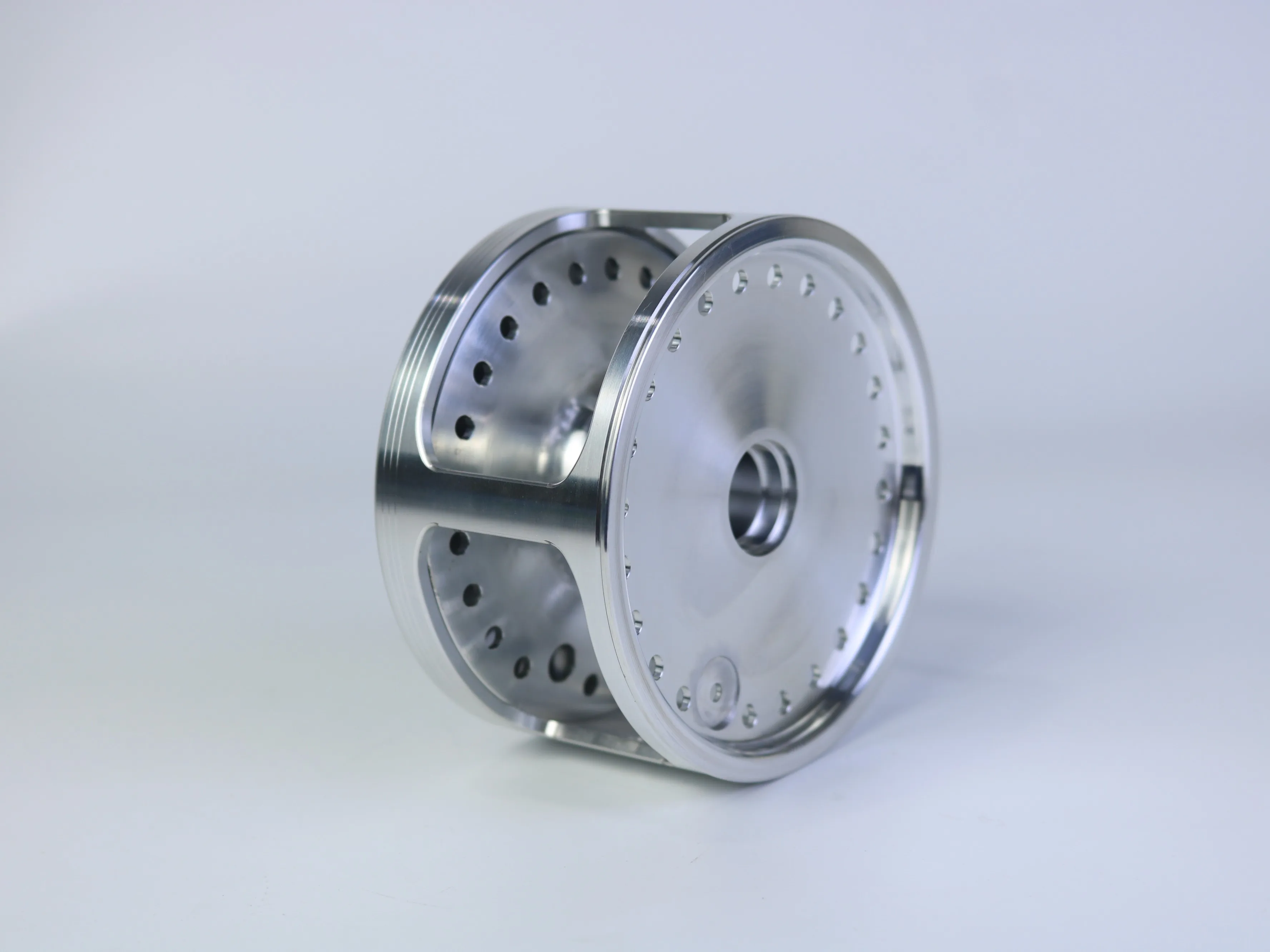
Long brackets and stepped supports often require more than one machining orientation. Each additional setup can introduce workholding cost and a new opportunity for datum-transfer error. A supplier should be able to explain how the part will be supported, located, and re-referenced between operations.
During design review, ask for feedback on:
- The preferred primary locating surface;
- Whether the part can be machined with stable support beneath thin or overhanging sections;
- Which features can be completed in one setup;
- Whether the hole pattern and mating faces can be related to the same datum structure;
- Whether soft jaws, a fixture, or a sacrificial support may be required for repeat production.
Complex CNC equipment can machine multiple sides or combine turning and milling operations in some cases, but that capability does not remove the need for sound workholding and datum planning. A more capable process may be justified for a complex geometry; it should not be assumed to be the lowest-cost option before the supplier reviews the complete part.
5. Treat material and surface finish as functional decisions
The image shows bright metallic surfaces, but appearance alone does not identify the alloy or confirm a finish. The material should be selected from the bracket's load, stiffness, corrosion, temperature, wear, electrical, and weight requirements.
The RFQ should state the exact material designation or an approved alternative policy. “Aluminum” or “stainless steel” may be insufficient when the design depends on strength, machinability, corrosion resistance, heat treatment, or finishing behavior.
Surface finish should also be connected to purpose:
- A mating face may need a controlled finish for contact or alignment.
- A threaded or sliding feature may need burr removal and edge control.
- A visible surface may require a cosmetic standard in addition to a numerical roughness requirement.
- A part exposed to a corrosive environment may need a specified treatment and confirmation of masking areas.
Avoid specifying a premium finish on every surface if only selected faces affect function or appearance. The drawing should identify critical areas, protected areas, and acceptable non-functional marks separately.
6. Make the RFQ complete enough for comparable quotations
A supplier cannot price the same part consistently when each bidder receives a different definition of the requirement. A practical CNC bracket RFQ package should include:
Controlled design data
Revision-controlled 3D CAD data, plus a 2D drawing with units, datums, tolerances, threads, finishes, and inspection notes.
Material and quantity
Material grade, approved substitution policy, prototype or production quantity, and annual usage or release pattern when available.
Secondary operations
Required finishing, heat treatment, marking, deburring, assembly, packaging, and protection requirements for finished surfaces.
Quality and timing
Required certificates or inspection reports, delivery milestones, and the quotation validity period requested by the buyer.
Include a clear list of critical-to-function dimensions or characteristics. When a supplier asks about a missing thread standard, unclear datum, or undefined cosmetic requirement, treat the question as engineering information rather than administrative friction. It often reveals where the drawing does not yet control the outcome.
7. Check inspection against the actual risk
Inspection should be proportional to the part's function. A bracket with a critical hole pattern and a controlled mounting face may require a different inspection plan from a simple support with clearance holes.
Before production, align with the supplier on which dimensions will be inspected, what datum reference will be used, whether first-article or sample inspection is needed, which features need a report rather than an in-process check, and whether a CMM, gauge, height measurement, thread gauge, or another method is appropriate.
Measurement quality includes uncertainty considerations. In practical purchasing terms, a reported number is more useful when the feature definition, datum reference, instrument or method, and acceptance requirement are also clear.
8. Common mistakes that create avoidable cost
1. Vague drawing
A 3D model communicates geometry, but it may not fully define functional tolerances, surface requirements, threads, or inspection expectations. Use the drawing to identify what matters.
2. Tight tolerance everywhere
A blanket precision requirement can push suppliers toward additional operations without improving assembly. Allocate tighter controls only to interfaces and performance-critical features.
3. Ignoring the mating part
A bracket cannot be evaluated as an isolated solid when its purpose is to mount another component. Provide the interface pattern or key mating dimensions.
4. Undefined finish
Material substitutions and finishing assumptions can make quotations appear comparable when they are not. State the grade, treatment, masking, and cosmetic expectations.
5. Comparing price first
A lower quotation may exclude inspection documents, finishing, deburring, packaging, or fixture work. Normalize the technical scope before selecting a supplier.
9. A practical review checklist for engineers and buyers
- The functional datums reflect how the bracket is assembled.
- Every hole has a defined purpose and standard.
- The hole pattern is controlled relative to the mating features.
- Internal corners, pockets, and slots are accessible to practical tooling.
- Thin walls and overhangs have adequate support during machining.
- Critical tolerances are limited to features that need them.
- Material and surface finish are explicitly defined.
- Inspection requirements match the assembly risk.
- Prototype and production quantities are both stated when known.
- All suppliers receive the same revision-controlled package.
This checklist can shorten quotation discussions and reveal design changes before they become production problems.
10. Frequently asked questions
Are CNC machined mounting brackets better than sheet metal brackets?
Neither process is universally better. CNC machining can be attractive when the bracket requires solid geometry, precise interfaces, integrated steps, pockets, or controlled hole relationships. Sheet metal may be more efficient for suitable thin-gauge bent forms and larger quantities. The right choice depends on geometry, volume, material, tolerances, strength, and finishing requirements.
What information should I send for a CNC bracket quotation?
Send a revision-controlled CAD model, a complete 2D drawing, material, quantity, finish, critical tolerances, inspection requirements, and delivery expectations. Include mating-part information whenever hole alignment or interface fit is important.
Should every mounting hole have a tight positional tolerance?
No. Tight positional control should be linked to the function of the hole. A locating hole, dowel interface, or controlled mating pattern may need more attention than a clearance hole with generous assembly clearance.
Can the exact material be identified from a product photograph?
No. Similar metals can have similar appearances, and a dark or reflective surface may result from several possible treatments. Confirm material through the drawing, purchase specification, supplier documentation, and, when required, the appropriate verification process.
Conclusion: design the bracket and the RFQ together
A reliable CNC machined mounting bracket begins with a clear functional definition. Once the locating surfaces, hole purposes, tool access, tolerance priorities, material, finish, and inspection plan are aligned, the supplier can give a more meaningful DFM response and a more comparable quotation.
For a custom bracket, the next step is not to guess a universal tolerance or select a supplier based on a single unit price. Share the controlled drawing and CAD model, identify the features that matter to assembly, and ask the manufacturer to review the design before production.
Have a custom bracket to manufacture?
Share your 2D drawing or 3D CAD file with PFTWORLD to discuss manufacturability, specifications, inspection requirements, and quotation scope.
Discuss Your CNC Machining Project