 EN


How to Design CNC Machined Brackets and Linkage Components for Lower Cost and Reliable Fit
A practical engineering guide for OEM buyers, product designers, and procurement teams who need machined brackets, mounting supports, linkage arms, or pivot components that can be quoted, manufactured, inspected, and assembled with fewer surprises.
The short answer: design the component around its functional datums and mating interfaces first, then simplify any feature that does not need special tooling, extra setups, or unnecessarily tight tolerances. A strong RFQ should make those decisions visible to every supplier.
Why These Components Need More Than a Basic Drawing
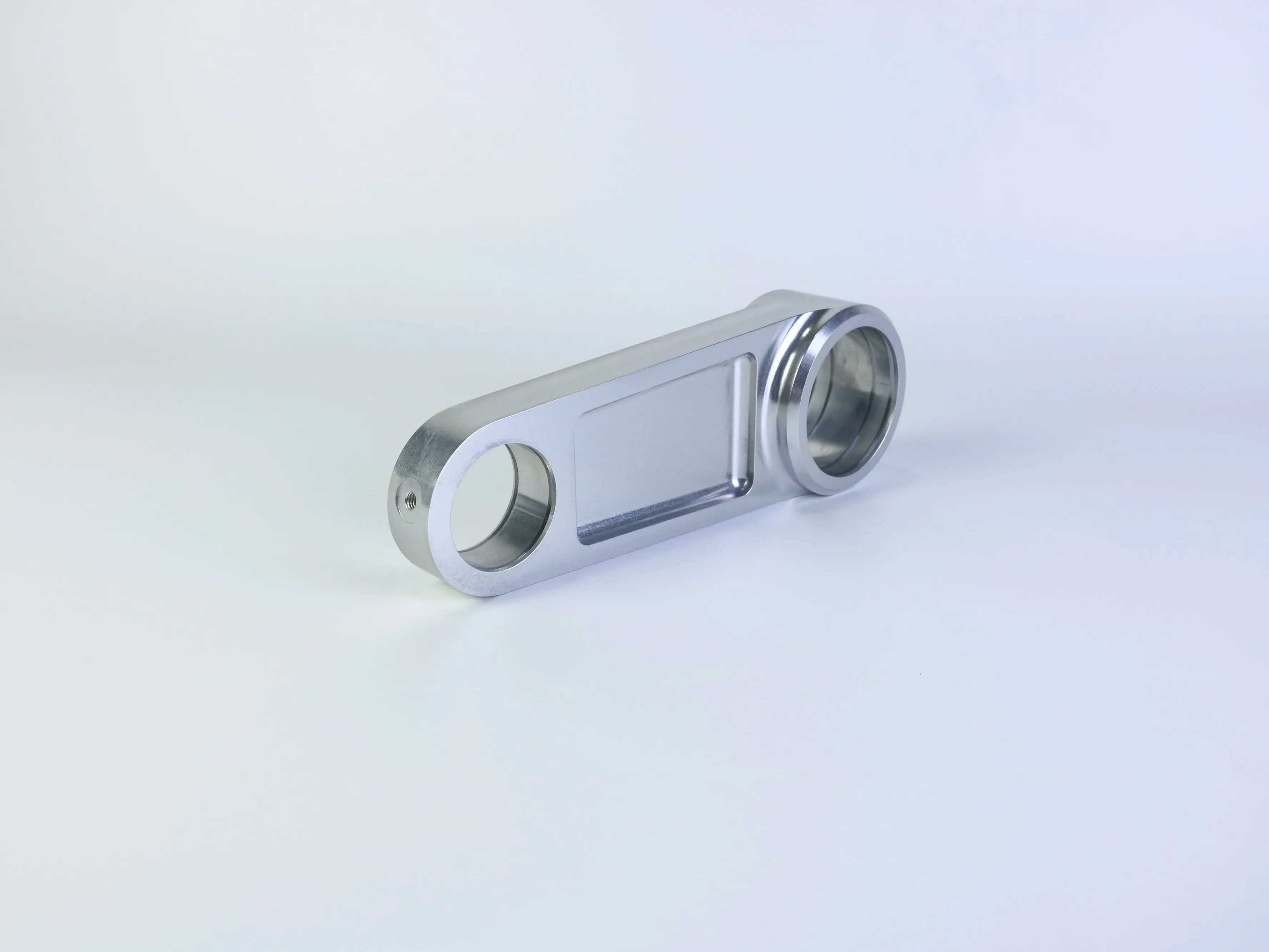
A CNC machined bracket or linkage component may appear simple: a plate, several holes, a pocket, and a curved or cylindrical feature. In production, those details control more than appearance. They influence tool access, workholding, machining time, positional accuracy, inspection, and the way the part fits with pins, shafts, bearings, fasteners, or a mating assembly.
Bracket and linkage designs often combine mounting holes, bores, pockets, openings, bosses, threads, and curved supports in one compact component. The manufacturing challenge is controlling the relationship between features after clamping, rotation, machining, deburring, finishing, and inspection. A hole can have an acceptable diameter yet fail assembly if its location is referenced from the wrong datum; a thin wall can measure correctly while clamped, then flex after material is removed.
Start with Functional Datums and Interfaces
Before selecting material or requesting a quotation, identify the surfaces and features that control assembly. For a mounting bracket, this may be the base face and mounting-hole pattern. For a linkage component, it may be the center distance between two bores, the axis of a pivot hole, or the relationship between a machined seat and a reference face.
A practical drawing separates critical characteristics from non-critical dimensions. Not every edge needs the same tolerance as a bearing seat or pivot-hole location. Tight tolerances across the entire part can increase machining and inspection cost without improving function.
Define primary, secondary, and tertiary datums; locate important holes from them; and state perpendicularity, parallelism, concentricity, or fit requirements only where the assembly needs them. Also identify surfaces used for clamping, sealing, sliding, or installation.
A 3D CAD model communicates geometry, while a matching 2D drawing should define threads, critical tolerances, finishes, datums, inspection notes, and acceptance requirements.
Design Holes for Access, Depth, and Inspection
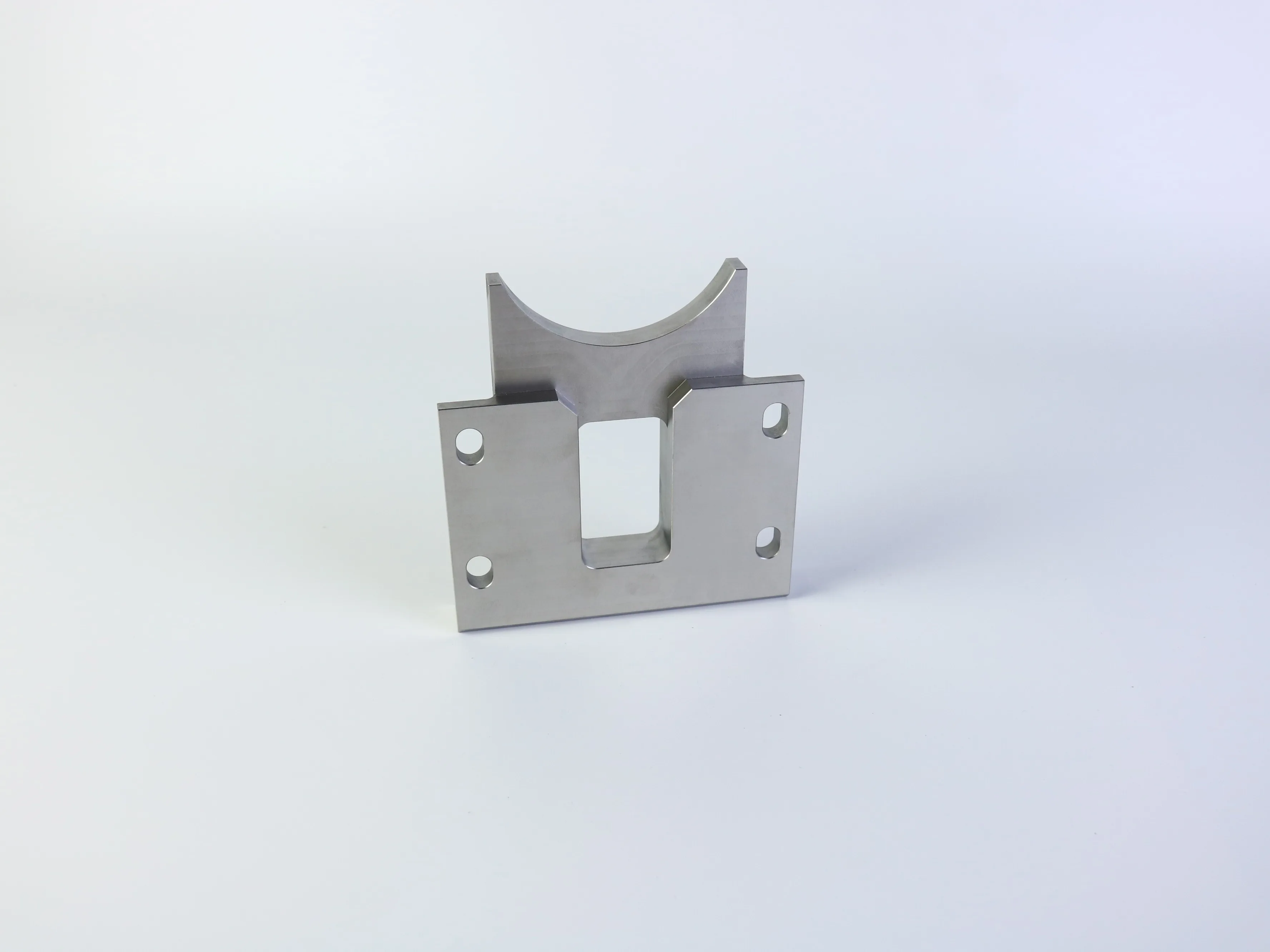
Holes are often the most important features in a bracket or linkage because they connect the part to the rest of the assembly. Their design should consider more than nominal diameter.
Through holes and blind holes
Through holes are usually easier to clean and inspect, but blind holes may be necessary for clearance, sealing, or a specific assembly arrangement. A drilled blind hole normally has a drill-point geometry at the bottom, while a milled or bored feature may have a different bottom form. If the bottom condition affects seating or travel, specify it on the drawing rather than leaving it to assumption.
Deep holes and critical bores
As hole depth increases relative to diameter, chip evacuation, tool rigidity, straightness, and inspection become more demanding. Deep holes may require special drilling or machining from more than one side. For a critical bore, specify diameter, depth, axis, location, and fit or surface condition. Identify the mating component; “precision hole” is not an acceptance criterion.
Hole location and setup planning
If holes on different faces must align, ask how the part will be located and how the relationship will be verified. Features machined in one setup generally have a simpler positional relationship than features that depend on several re-clamp operations. A multi-axis process may solve an access issue, but it can also change the quote, fixturing plan, and inspection method.
Use Internal Radii and Make Pockets Manufacturable
Standard CNC milling cutters are cylindrical, so an internal milled corner naturally receives a radius. For a bracket pocket or linkage relief, the most economical radius is usually one that matches an available cutter without compromising clearance. If a mating part truly needs a square internal corner, consider a relief, T-bone feature, broached section, EDM operation, or a design change before releasing the drawing.
External edges are different. A small chamfer can help with deburring, handling, and assembly while generally being simpler than a decorative external radius. State whether the edge treatment is functional, cosmetic, or simply intended to remove a sharp edge.
Deep, narrow pockets require long-reach tools that are more prone to deflection and vibration. Use the largest practical cutter diameter and the shortest practical reach. If a wall does not need to be thin for clearance or weight, add thickness or use ribs and buttresses. If it must remain thin, identify it as a critical feature and discuss workholding and inspection before production.
When a pocket exists only to reduce weight, compare its benefit with its machining cost. A simpler open profile, larger corner radius, or shallower pocket may provide most of the functional benefit while reducing tool changes and cycle time.
Select Material and Finish from the Application
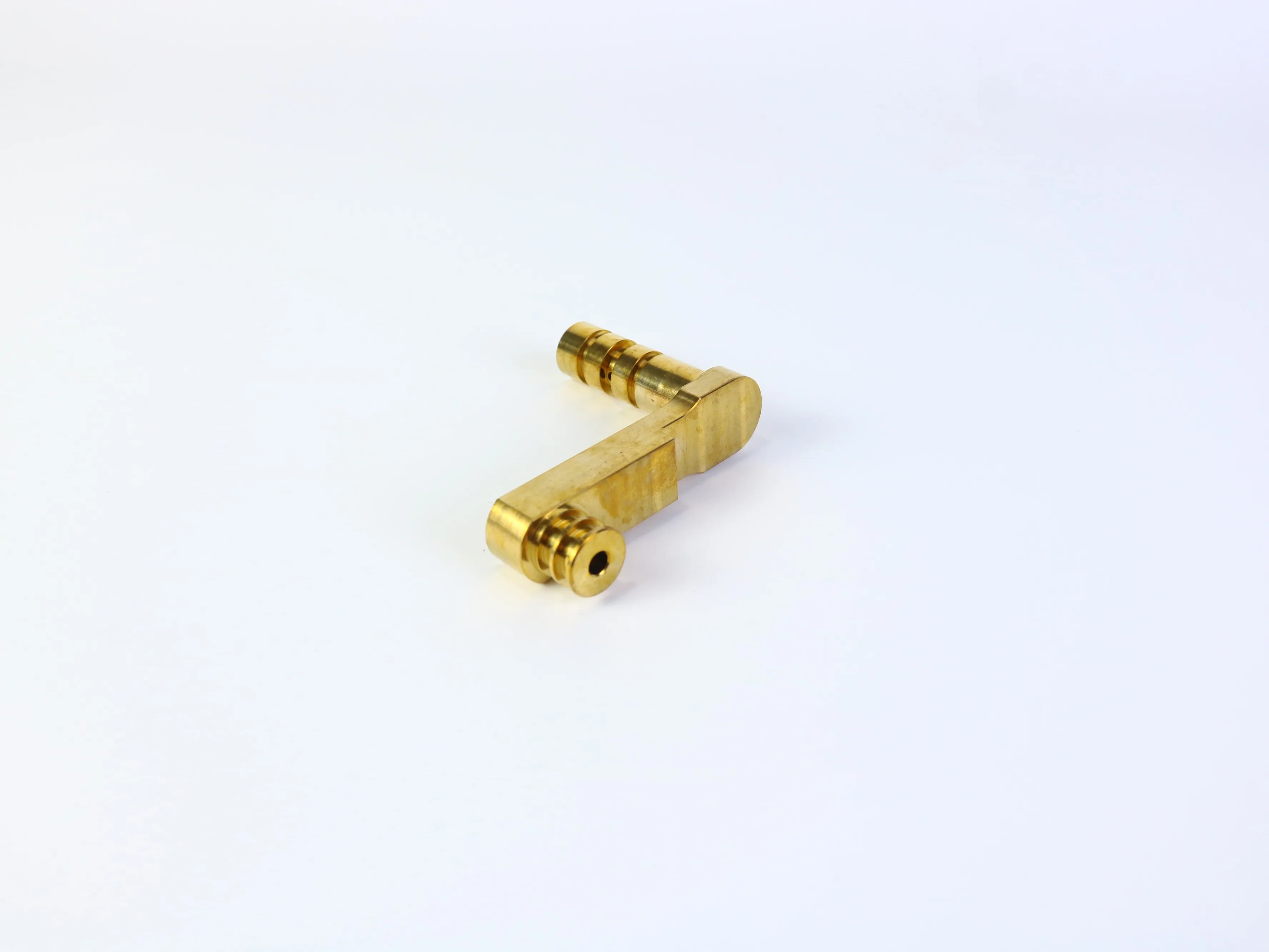
Bright metallic surfaces can suggest a finish, but a photograph cannot confirm aluminum, stainless steel, brass, heat treatment, coating, or mechanical properties. Select the material from the application requirements:
- Strength and stiffness: define loads, deflection limits, and relevant safety factors.
- Wear and sliding contact: identify whether a pin, shaft, bushing, or bearing moves against the part.
- Corrosion environment: consider moisture, chemicals, salt, temperature variation, and cleaning conditions.
- Weight: confirm whether mass reduction is functional or only preferred.
- Appearance: state whether the finish is cosmetic, protective, or both.
- Post-processing: specify anodizing, passivation, plating, polishing, masking, or other treatments.
The drawing should state the material grade and condition, not simply “metal” or “aluminum.” Identify critical surfaces that must remain uncoated or be measured after finishing, especially bearing seats, threads, mating bores, and sliding surfaces.
Treat Tolerances as a Functional Budget
A common quotation mistake is applying tight tolerances to every dimension. Tolerance should reflect function, process capability, and inspection need. A tighter tolerance may require additional finishing operations, slower cutting, dedicated workholding, temperature control, or more detailed inspection. It can also create unnecessary rejection risk when the assembly does not need that level of precision.
- Critical features: define the size, location, form, and relationship needed for assembly or motion.
- Supporting features: use practical tolerances that preserve fit and appearance.
- Non-critical envelope dimensions: avoid unnecessary precision.
- Surface requirements: specify roughness only where it affects sealing, sliding, fatigue, appearance, or measurement.
If a hole is intended for a press fit, clearance fit, or transition fit, state the design requirement and identify the mating part. Do not expect a supplier to infer a critical tolerance from a photograph or an unlabeled CAD model.
Plan Inspection Before Machining Begins
Inspection should influence the design and fixturing plan, not only final release. A bracket may require hole position relative to a base datum, contact-face flatness, and opening size. A linkage component may depend on center distance, bore diameter, concentricity, and surface condition.
An RFQ or drawing should clarify which dimensions are critical, the inspection standard or sampling expectation, whether a first-article report is required, which measurement datums must be used, and whether inspection occurs before or after surface treatment. Avoid requesting a generic “full inspection” without defining the documentation required. Different suppliers may interpret that phrase differently, making quotations difficult to compare.
What to Include in a CNC Machining RFQ
A complete RFQ helps a manufacturer evaluate price and feasibility at the same time. For CNC machined brackets and linkage components, include:
- Revision-controlled 3D CAD file and matching 2D drawing when tolerances, threads, finishes, or inspection notes matter;
- Material grade and condition, plus prototype, pilot-run, and production quantities;
- Critical dimensions, datums, geometric relationships, and thread requirements;
- Surface finish, coating, plating, anodizing, passivation, deburring, and edge-break requirements;
- Inspection documentation, acceptance criteria, packaging, marking, traceability, and delivery requirements;
- Any known assembly, mating, or service-life constraint.
Ask the supplier to identify quotation assumptions. The most useful quote is not always the lowest price; it clearly states included material, process, finish, inspection scope, quantity, and exclusions.
A Practical Design Review Checklist
- Are the functional datums clearly defined?
- Are critical holes and bores located from those datums?
- Can the main features be reached with practical tools?
- Are internal corners compatible with cutter radii?
- Are deep pockets, deep holes, thin walls, and undercuts identified?
- Can the part be held without distorting a functional surface?
- Are tolerances limited to features that need them?
- Is the material grade confirmed independently of visual appearance?
- Is the finish compatible with assembly and inspection?
- Does the drawing match the CAD revision?
- Are inspection records and acceptance criteria explicit?
- Can another supplier quote the same requirement without guessing?
Choose a Machining Partner That Reviews the Whole Requirement
A capable machining partner should contribute more than a unit price. During quotation, the supplier should discuss tool access, setups, material availability, finishing risks, inspection points, and features that may increase cost or reduce repeatability. PFTWORLD provides relevant CNC machining and custom machined-part service pages; confirm project-specific capabilities before including them in a purchase order or capability claim.
Frequently Asked Questions
Are CNC machined brackets suitable for prototypes and production?
They can be, depending on geometry, material, quantity, and production economics. CNC machining is useful when a part needs engineering material, functional holes, accurate interfaces, or design iterations before a larger production commitment. The final production process should be evaluated against quantity, cycle time, tooling, and alternatives.
Can a CNC mill make perfectly sharp internal corners?
Not usually with a standard round end mill. Internal corners normally receive a radius. If a sharp corner is functionally necessary, discuss a relief or special process before finalizing the design.
What is more important: hole diameter or hole position?
It depends on the assembly. A pin may require a controlled diameter, while a bolt pattern may be more sensitive to positional accuracy. A bearing seat may require both size and form control. The drawing should define the functional requirement instead of applying one tolerance to every hole.
Do I need both a 3D model and a 2D drawing?
A 3D model communicates geometry. A 2D drawing is strongly recommended when the part has critical tolerances, threads, surface-finish requirements, datum relationships, inspection notes, or special acceptance conditions. The files should match the same revision.
Can the material be identified from a product photo?
No. A photograph may suggest a metallic appearance or finish, but it cannot reliably confirm a material grade, heat-treatment condition, coating, or mechanical property. Those requirements must be specified and verified through the purchasing and quality process.
Conclusion
CNC machined brackets and linkage components become easier to quote, manufacture, and inspect when the design separates function from appearance. Define the datums and interfaces first. Use practical internal radii, avoid unnecessary deep or thin features, plan tool access and setups, assign tolerances according to function, and provide enough drawing and inspection information for suppliers to quote the same requirement.
Have a Custom Bracket or Linkage Component to Manufacture?
Share your 3D CAD file, drawing, material, quantity, critical tolerances, finish, and inspection requirements with PFTWORLD to discuss manufacturability and quotation requirements.
Explore CNC Machining ServicesFinal material, process, tolerance, inspection, delivery, and contact arrangements should be confirmed for the specific project before purchase.
Table of Contents
- Why These Components Need More Than a Basic Drawing
- Start with Functional Datums and Interfaces
- Design Holes for Access, Depth, and Inspection
- Use Internal Radii and Make Pockets Manufacturable
- Select Material and Finish from the Application
- Treat Tolerances as a Functional Budget
- Plan Inspection Before Machining Begins
- What to Include in a CNC Machining RFQ
- A Practical Design Review Checklist
- Choose a Machining Partner That Reviews the Whole Requirement
- Frequently Asked Questions
- Conclusion
- Have a Custom Bracket or Linkage Component to Manufacture?