 EN


PFTWORLD | 7 Swords Precision Manufacturing
CNC Machined Stainless Steel Flanges: Design, Inspection, and RFQ Guidance
A practical guide to specifying flange-style components with stepped bores, bolt-hole patterns, turned features, and inspection requirements.
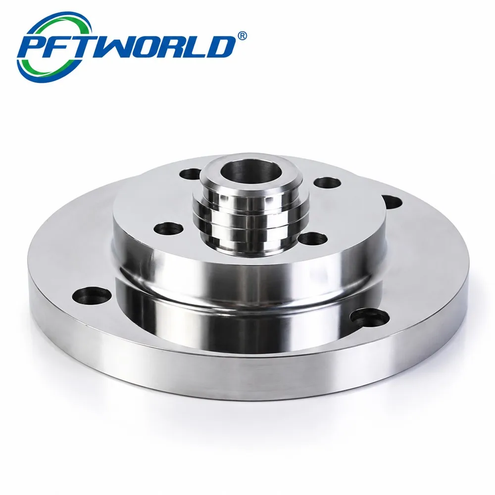
Flange-style components often look simple because their dominant form is round. In practice, they can combine several demanding requirements in one compact part: a stable mounting face, a concentric bore, stepped diameters, threaded or counterbored features, a controlled bolt-hole pattern, clean edge transitions, and a surface finish suitable for assembly. A small error in datum selection, hole location, bore size, or perpendicularity can create leakage, runout, uneven clamping, or difficult installation.
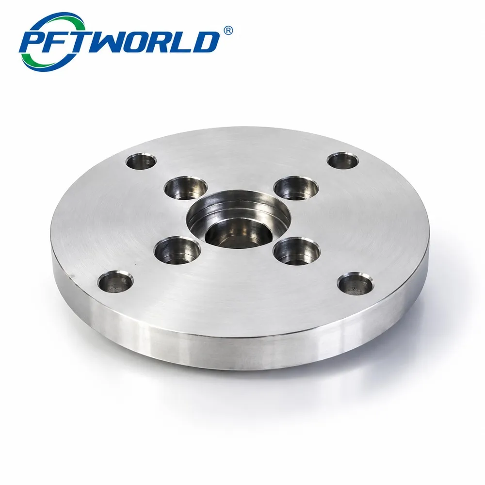
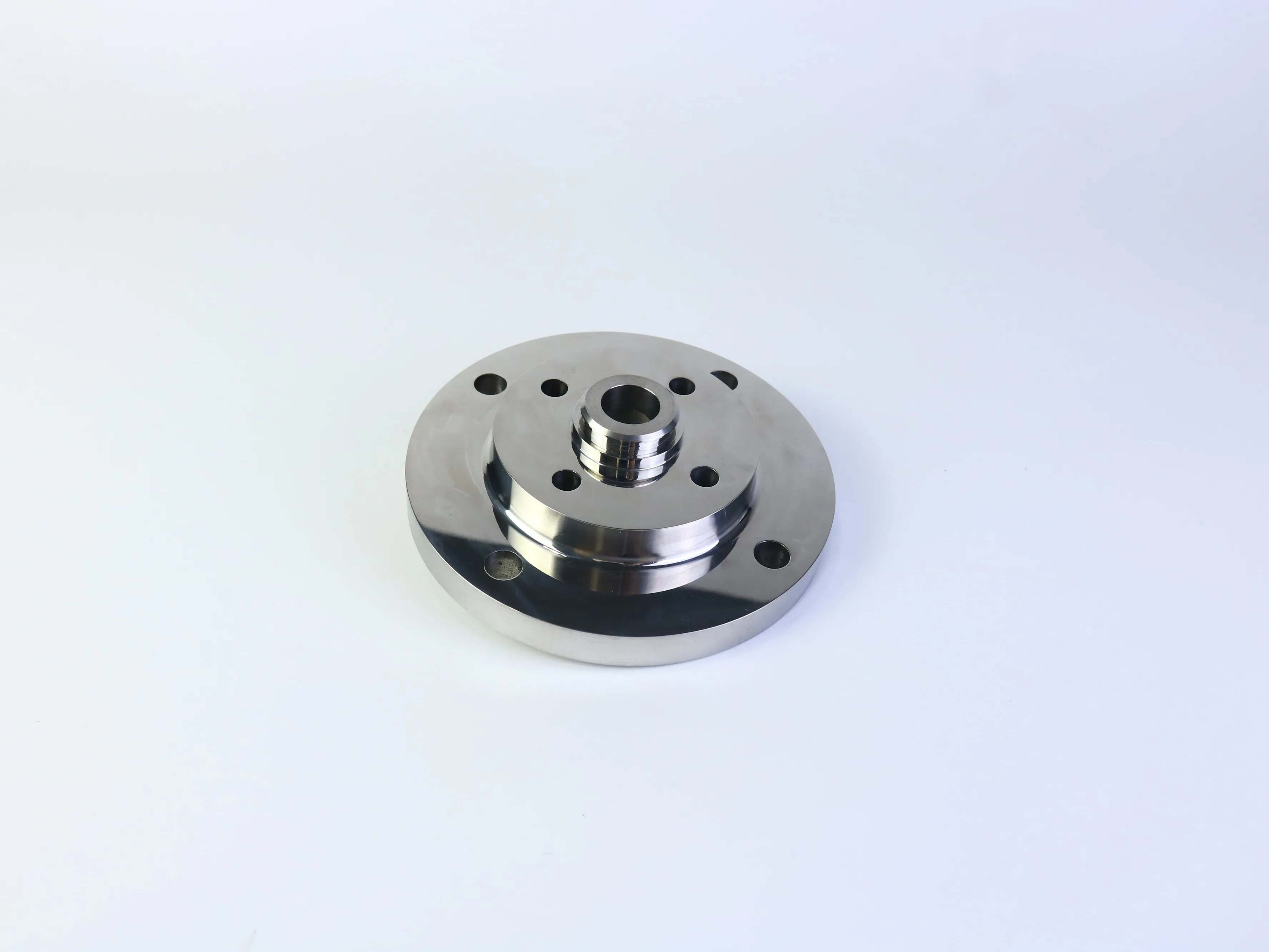
The images in this article show polished, flange-style components produced with turned and milled features. They are useful for discussing design and sourcing decisions, but an image alone cannot confirm the exact alloy, dimensions, tolerance class, surface treatment, or end use. Those details should be controlled by the 2D drawing, 3D CAD model, material specification, and inspection plan.
The short answer: define function before tightening tolerances
For a reliable CNC machined flange, define the functional datum, identify the locating bore or pilot, control the bolt-hole pattern with the correct geometric callout, and separate critical features from cosmetic requirements. Request a first-article inspection plan before production if the flange controls alignment, pressure, rotation, or an assembly interface. Tight tolerances should be applied to features that affect function, not automatically to every dimension.
What engineers should identify on a flange drawing
Before requesting a quote, describe the part as a functional interface rather than only as a round metal disc. The following information helps a manufacturer select the process, tooling, inspection method, and finishing route.
- Identify the primary mounting face and the datum axis. The datum scheme should reflect how the part is located in the final assembly.
- Specify the pilot diameter, central bore, counterbore, shoulder, or register that controls concentricity with the mating component.
- Define the bolt-hole quantity, pitch-circle diameter, angular spacing, hole size, depth, thread standard, and any counterbore or countersink requirement.
- Separate functional tolerances from general tolerances. A bore fit, axial face, or bolt pattern may need geometric control even when the rest of the part can use a broader tolerance.
- State the material grade and condition. Stainless steel options such as 303, 304, or 316 may behave differently during turning, drilling, deburring, and finishing.
- Add surface-finish, passivation, cleaning, marking, packaging, and traceability requirements when the component enters a controlled assembly or regulated environment.
How the machining process is normally planned
The exact routing depends on size, material, quantity, and tolerances, but a flange with turned diameters and milled or drilled hole patterns commonly follows a controlled sequence. Starting with the correct sequence is important because each setup can introduce a new source of runout or positional error.
- Material and blank review. Confirm the grade, bar or plate condition, stock allowance, and material documentation. The blank should provide enough allowance for facing and finishing without creating unnecessary cycle time.
- Turning of the round profile. CNC turning can establish the outside diameter, front and back faces, steps, shoulders, grooves, and the initial central bore. A stable chucking strategy helps control axial runout and concentricity.
- Drilling and boring. The central feature may require drilling followed by finish boring or reaming, depending on the specified fit and surface requirements. The tool path should avoid leaving a sharp burr at an intersecting shoulder.
- Hole-pattern machining. The part is located from the functional datum or pilot before the bolt holes are drilled, tapped, counterbored, or countersunk. When the pattern controls assembly alignment, true position or another appropriate geometric tolerance should be evaluated rather than relying only on coordinate dimensions.
- Deburring and cleaning. Hole intersections, grooves, and shoulder transitions need controlled deburring. Ultrasonic or aqueous cleaning may be considered when chips, abrasive residue, or handling contamination could affect the assembly.
- Finishing and final inspection. Passivation, polishing, plating, or another specified treatment should be completed under a controlled process. Final checks should verify critical dimensions, bore condition, face runout, bolt-hole location, and visible damage.
Inspection points that protect assembly performance
A flange should be inspected against the way it functions. A dimensional report that lists only outside diameter and thickness may miss the feature that actually causes an assembly problem. Ask the supplier to align the inspection plan with the drawing datums and critical interfaces.
For complex or tolerance-sensitive parts, a coordinate measuring machine can verify three-dimensional relationships between the bore, faces, and hole pattern. PFTWORLD's capability snapshot lists CMM and 2D measurement resources, with standard machining tolerance information of approximately ±0.01 mm and special-area capability subject to engineering review. The applicable tolerance for any specific flange must be confirmed from the approved drawing and inspection plan.
How datum strategy affects flange performance
Datum selection is not a formality. It determines how the part is located during machining and how the inspection results relate to the assembly. If the mating assembly locates from a central pilot, the pilot and its axis should normally be treated as a functional reference. If the flange is clamped against a face, that face may need to establish the axial datum. The drawing should make this logic visible instead of leaving the supplier to infer it from scattered dimensions.
A useful design review asks three questions: Which feature centers the flange? Which face controls axial seating? Which bolt holes control the final connection? The answers guide the relationship between size tolerances, perpendicularity, runout, and position. They also determine whether the part should be inspected on a CMM, with dedicated gauges, or by a combination of methods. A hole pattern can have individually correct diameters and still fail to assemble if its location is related to the wrong reference.
For this reason, a supplier should receive the complete drawing rather than a cropped screenshot of the part. The drawing revision, datum symbols, material condition, geometric controls, and notes are part of the manufacturing definition. When a design is still under development, clearly mark the file as preliminary and identify which requirements are open for engineering review.
Design-for-manufacturability checks before you request a quote
Many flange problems can be prevented before machining starts. Review the drawing with the supplier and ask for feedback on the following items:
- Avoid unnecessarily deep, narrow grooves that are difficult to reach with standard tooling.
- Add practical edge breaks or chamfers where they do not interfere with sealing or locating functions.
- Check that drill clearance, tool access, and chip evacuation are adequate for every hole and pocket.
- Do not apply a very tight tolerance to a non-functional cosmetic surface when a general tolerance is sufficient.
- Specify whether a hole is through, blind, tapped, counterbored, or countersunk. Ambiguity at this stage creates quotation and inspection risk.
- For stainless steel, discuss work-hardening risk, tool condition, cutting strategy, and the required finishing route with the machining engineer.
What to include in an RFQ for CNC machined flanges
A complete RFQ allows a manufacturer to quote the real scope instead of guessing. Include the following whenever possible:
Design files: a 2D drawing with revision, units, datums, tolerances, material, finish, and inspection notes, plus a STEP or other neutral 3D model when available.
Quantity: prototype quantity, pilot quantity, expected repeat order, and annual demand if known.
Quality documents: material certificate, first-article report, full dimensional report, surface-treatment certificate, or third-party inspection if required.
Commercial details: packaging, marking, destination, preferred Incoterm, target delivery window, and any confidentiality or compliance requirements.
Shenzhen Perfect Precision Products Co., Ltd., operating under 7 Swords and Swords Precision, is a custom OEM/ODM manufacturer established in 2012. Its verified company snapshot lists more than 79 machines, more than 100 professional staff, ISO9001:2015 and ISO13485:2016 quality-management certifications, and production capacity above 300,000 pieces per month. These figures describe company-level capability; the feasibility, price, lead time, and inspection scope for a particular flange still depend on the drawing and order requirements.
How to compare suppliers for a production-ready flange
A technically strong quotation should make comparison easier, not hide the assumptions. Check whether each supplier has identified the material grade, machining route, secondary operations, inspection scope, packaging, and delivery basis. Compare like with like: a quote that excludes passivation, a dimensional report, or protective packaging is not directly comparable with one that includes them.
Ask how the supplier will control the relationship between the central bore, mounting face, and bolt-hole pattern. Ask which dimensions will be checked during first article inspection and what evidence will accompany the shipment. If the part is used in a medical, aerospace, automotive, or other controlled application, request the exact certificates and revision status needed for your qualification process rather than accepting a general statement of compliance.
PFTWORLD states that it operates as a custom OEM/ODM manufacturer and supports CNC machining, inspection, surface finishing, and related manufacturing processes. Company facts supplied for this article identify ISO9001:2015 and ISO13485:2016 as verified certifications, while other certifications listed in the source material require confirmation before publication or procurement reliance. This distinction is important: a transparent supplier should separate verified capability from a capability that still needs document review.
Frequently asked questions
Can a flange be machined from stainless steel?
Yes. Stainless steel grades can be evaluated for CNC turning, milling, drilling, boring, and finishing. The grade, heat condition, geometry, quantity, and required surface treatment should be confirmed before quoting because they affect tool selection, cycle time, and inspection.
What tolerance can be achieved?
The achievable tolerance depends on material, feature size, geometry, machine setup, thermal stability, and inspection method. A capability snapshot may state standard tolerance around ±0.01 mm and special areas around ±0.005 mm, but the supplier should confirm the specific drawing callouts rather than applying one tolerance to every feature.
Should I specify true position for bolt holes?
If the bolt-hole pattern controls assembly alignment, a geometric position requirement is often clearer than several independent coordinate dimensions. The correct datum structure, material condition, and inspection method should be reviewed by the design and manufacturing teams.
Can I request a prototype before volume production?
Yes. A prototype or first-article stage can confirm fit, bore condition, hole alignment, finish, packaging, and the inspection format before a repeat or higher-volume order. The drawing revision used for the prototype should be recorded to avoid uncontrolled changes.
What is the best way to start an inquiry?
Send the drawing, 3D model, material grade, quantity, finish, critical tolerances, delivery destination, and inspection requirements. If a drawing is not ready, provide clear photos, a dimensioned sketch, the intended function, and the features that control assembly.
Need a quote for a custom CNC flange?
Share your drawing or CAD file with the 7 Swords team for a review of manufacturability, material, tolerances, inspection, finishing, and quotation requirements.
Request a QuoteTechnical note: the photographs illustrate visible geometry only. Confirm material, dimensions, tolerances, certifications, inspection scope, and delivery commitments against the approved quotation and contract before production.
Table of Contents
- The short answer: define function before tightening tolerances
- What engineers should identify on a flange drawing
- How the machining process is normally planned
- Inspection points that protect assembly performance
- How datum strategy affects flange performance
- Design-for-manufacturability checks before you request a quote
- What to include in an RFQ for CNC machined flanges
- How to compare suppliers for a production-ready flange
- Frequently asked questions
- Need a quote for a custom CNC flange?