 EN


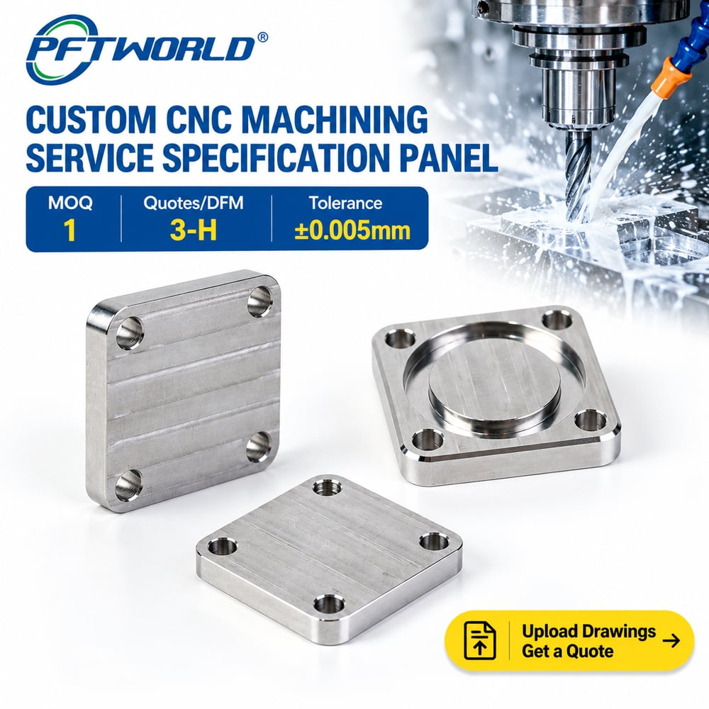
Custom CNC Machined Component
CNC-Machined Flange or Cover Plate for Defined Mechanical Interfaces
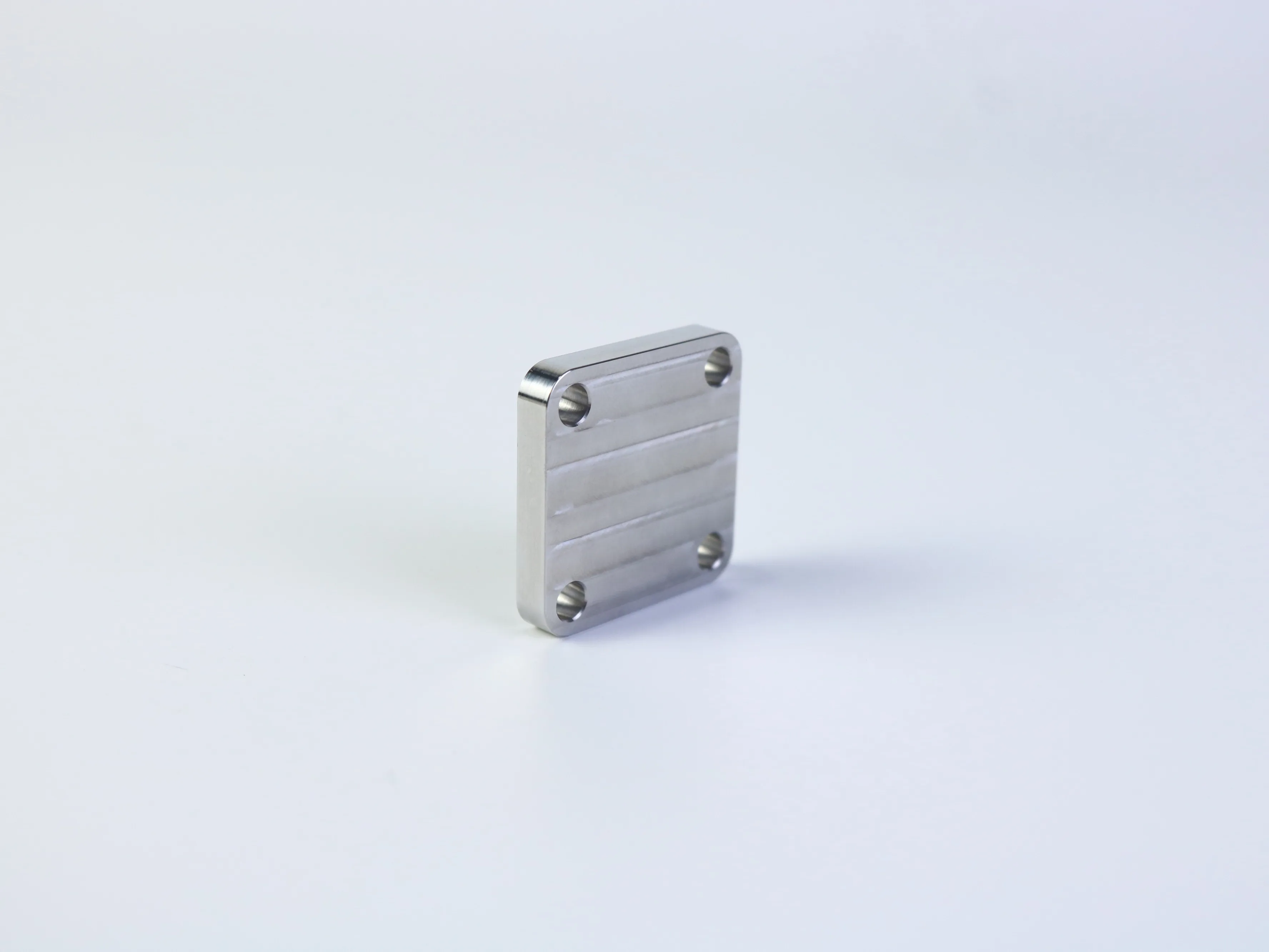
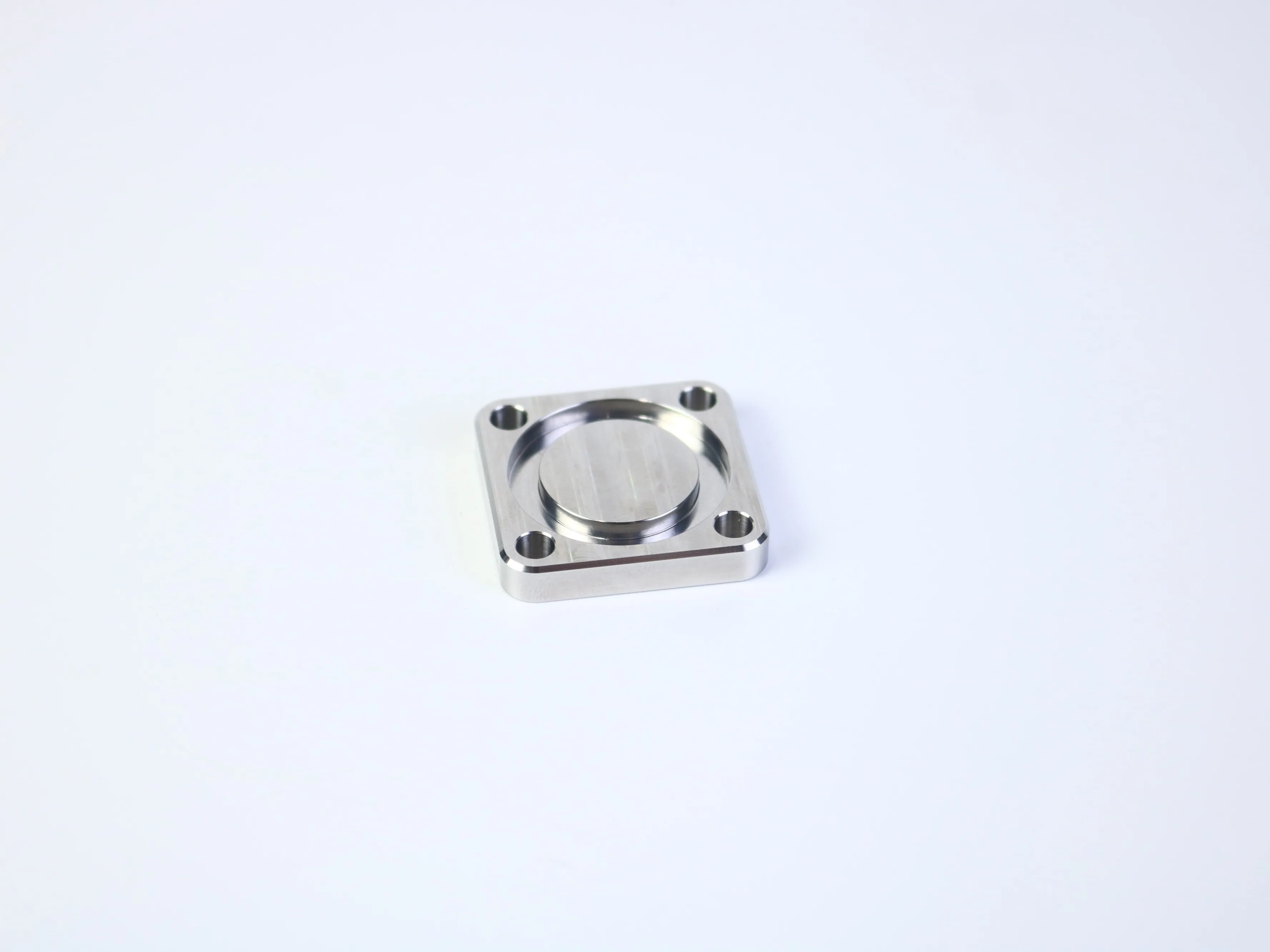
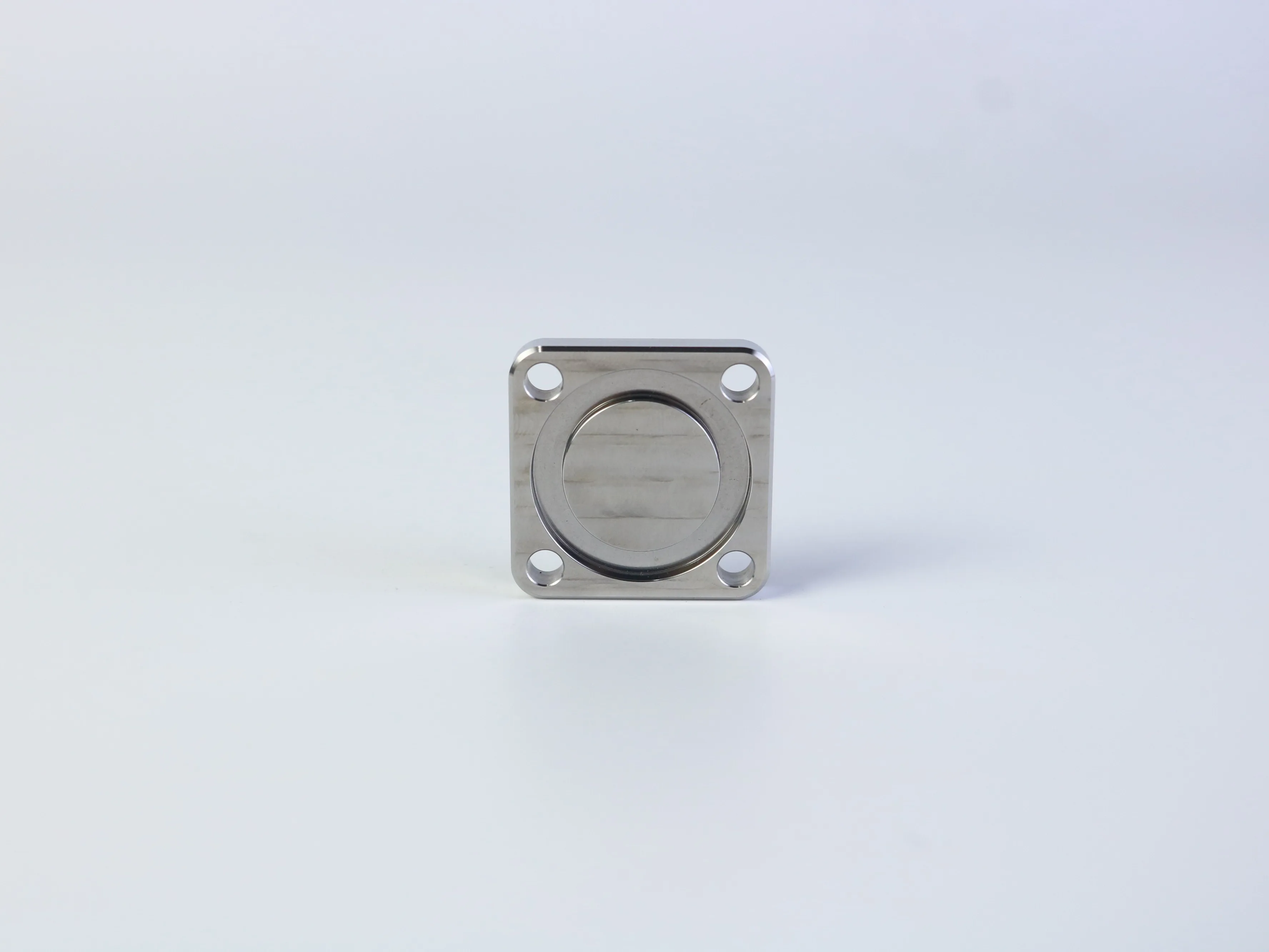
A plate with four corner mounting holes and a central circular feature can look straightforward. For an engineer or sourcing team, however, the important questions begin beyond the photograph: What does the centre feature do? Which dimensions control fit? Is the face used for locating, seating, clearance, or sealing? This product-page guide explains what to define before quoting a custom machined plate or flange-like component.
What should be specified before this part is quoted?
The short answer is: specify function first, then geometry, material, critical tolerances, surface requirements, and inspection evidence. A product photograph is useful for starting a discussion, but it cannot establish scale, alloy, hole size, feature depth, flatness, or process route. Those requirements belong in a drawing, CAD model, approved sketch, or written engineering specification.
For a component of this general form, the four-hole pattern may provide mounting or fastening, while the circular feature may support locating, clearance, seating, or sealing. These are engineering possibilities rather than conclusions from the image. The buyer should identify the mating component, load direction, environment, and assembly method before asking a supplier to confirm feasibility.
Define the interface, not only the outside shape
The most valuable information in an RFQ is the information that explains how the part must work. Start with the mating interface. Identify which face contacts another component, whether the central feature locates the part, and whether the four holes carry load, retain a cover, or establish an assembly position. If the plate is part of a sealed enclosure or fluid-handling assembly, state the sealing element, operating conditions, and relevant interface requirements rather than simply requesting a “smooth finish.”
Next, identify the datums and critical relationships. The position of each hole may matter relative to the centre feature, a reference edge, or a datum face. The central feature may need a defined diameter, depth, concentricity relationship, or fit. The face may need flatness or perpendicularity only when those characteristics affect assembly or performance. The correct callout depends on the function; tighter is not automatically better.
General CNC design guidance also treats tolerance, pocket depth, wall thickness, hole geometry, internal radii, and the number of setups as manufacturability and cost considerations. The applicable limits vary with material, part size, tooling, equipment, and production quantity. A supplier should review the actual drawing rather than applying a generic number to every part.
RFQ specification checklist for a four-hole machined plate
Use the following checklist to make the quotation request clear and technically useful. Each item should be confirmed against the application.
| Specification area | Information to provide |
|---|---|
| Overall geometry | Outside length and width, thickness, corner radius, edge treatment, and the approved 2D or 3D reference. |
| Mounting pattern | Hole quantity, hole type, diameter or thread, location method, pitch or bolt-circle relationship, and any countersink or counterbore requirement. |
| Central feature | Function, diameter, depth, step geometry, fit, datum relationship, and whether it is a bore, pocket, boss, locating seat, or sealing interface. |
| Material | Approved grade, condition, traceability needs, and any compatibility requirements related to load, temperature, corrosion, or process environment. |
| Critical requirements | Only the tolerances, flatness, perpendicularity, position, concentricity, or runout values that control fit and function. |
| Finish and inspection | Surface-finish requirement by face, deburring expectations, visual criteria, measurement method, inspection report format, and sample or first-article requirements. |
| Commercial context | Prototype or production quantity, target market, packaging needs, delivery constraints, and the next approved step for technical review. |
Why drawing quality affects quotation quality
A clear drawing helps a supplier separate cosmetic features from functional requirements. That distinction matters because every unnecessary tight callout can increase machining time, inspection effort, fixturing complexity, or scrap risk. Conversely, an omitted requirement can produce a part that looks correct but does not align, seat, seal, or assemble as intended.
For the pictured geometry, the relationship between the central circular feature and the four mounting holes deserves particular attention. If the centre is a locating feature, hole position may need to be controlled relative to it. If the face is a seal or sliding surface, finish and flatness may become more important than the appearance of the outer edges. If the component is simply a protective cover, the functional priorities may be different. The supplier needs the application logic to recommend a practical process and inspection plan.
Inspection language should also match the risk. A visual check may be appropriate for deburring or cosmetic marks, while critical hole position, feature size, or face condition may require defined instruments and a recorded report. Do not request a certification or measurement record without identifying the characteristic it is meant to verify.
Choose requirements by risk and function
A reliable specification does not need to make every feature equally complex. It needs to make the important features unambiguous. Begin by separating the part into functional zones: the mounting zone around the four holes, the central interface, the primary reference face, and the external profile. For each zone, ask what could cause assembly failure or service failure if it were out of position, too rough, too thin, or incorrectly finished.
For the mounting zone, confirm how fasteners are installed and what they must retain. A clearance hole, tapped hole, counterbore, and countersink create different assembly conditions. The drawing should identify the applicable standard or thread form where relevant, together with the location method and any positional relationship to the centre feature. “Four holes in the corners” is a useful visual description, but it is not a complete manufacturing requirement.
For the central interface, define the mating part and the desired result. A locating seat may require a controlled diameter and depth. A clearance pocket may need adequate relief but no precision fit. A sealing feature may need a groove profile, surface condition, and compatibility review for the selected seal. A cover interface may prioritise flatness and fastener seating. These functions can look similar in a photograph while requiring very different drawings and inspection plans.
The same principle applies to finish. If a face only needs to be visually consistent, a visual acceptance description may be sufficient. If it contacts a gasket, bearing, guide, or locating shoulder, the finish should be linked to that function and measured by an agreed method. Avoid using a generic “polished” or “smooth” request when the actual requirement is flatness, roughness, burr removal, or a defined coating.
Quantity and production intent should be stated early. A prototype may be used to validate fit, while a production order may require process consistency, sampling rules, traceability, and a repeatable inspection record. The supplier can then distinguish a design question from a production-control question and recommend an appropriate review sequence.
What to review when comparing supplier quotations
A lower quotation is not necessarily comparable to a higher one if the suppliers have interpreted the specification differently. Ask each supplier to confirm the material, manufacturing assumptions, critical dimensions, finish interpretation, inspection scope, packaging, and delivery basis. Any exclusion should be written down rather than left to an informal message.
Review whether the quotation identifies the same reference drawing and revision. Check that the quoted quantity, prototype or production status, and requested finish match the RFQ. If the supplier proposes a tolerance change, alternate material, substitute process, or different inspection method, treat it as a technical deviation requiring review—not as an automatic improvement.
For alignment-sensitive parts, ask how the supplier plans to establish datums and verify the relationship between the central feature and the mounting pattern. For sealing or sliding interfaces, ask which face is controlled and how the relevant condition will be measured. For cosmetic requirements, define what is acceptable under the agreed viewing conditions. A clear inspection plan makes the final acceptance discussion more objective.
This does not mean every RFQ needs a complex report. The level of evidence should match the consequence of failure. A simple protective cover may need basic dimensional and visual checks. A precision interface may require a more detailed dimensional report. The right question is not “How much inspection can be added?” but “Which evidence demonstrates that the part meets its intended function?”
A practical path from concept to supplier review
PFTWORLD’s public pages describe CNC machining and custom precision mechanical-part services. Whether this specific component is suitable for a particular process, material, tolerance, and quantity still depends on a drawing review and the supplier’s confirmed scope. The most efficient first step is therefore to share the best available technical reference, even if it is a redacted drawing, dimensioned sketch, or preliminary CAD model.
- Identify the part’s function and mating components.
- Mark the datums and the features that control fit or alignment.
- Confirm material, quantity, finish, and inspection expectations.
- Ask for a feasibility review that separates confirmed requirements from open questions.
- Approve the final manufacturing and inspection plan before production.
This workflow keeps the conversation focused on engineering decisions instead of assumptions based on a photograph. It also gives procurement teams a clearer basis for comparing quotations, because suppliers are responding to the same defined requirements.
Frequently asked questions
Can the material be identified from the product photographs?
No. The photographs show a reflective metallic-looking component, but they do not verify an alloy, heat treatment, coating, or material condition. Use an approved material specification and, where required, traceability documentation.
Is the circular feature an O-ring groove or a locating pocket?
Its function cannot be established from the images. It could be consistent with several interface designs. Confirm the purpose, dimensions, sealing element, fit, and datum relationship on the drawing.
What information should accompany a quotation request?
Provide the drawing or CAD reference, material, quantity, critical tolerances, finish, inspection requirements, application context, and delivery constraints. A preliminary sketch is better than a photograph alone, provided its provisional dimensions are clearly marked.
Should every dimension receive a tight tolerance?
Usually not. Tolerances should reflect fit and function. Overly tight requirements can add cost and inspection burden, while missing functional requirements can create assembly risk. Review the tolerance scheme with a qualified engineer and the selected supplier.
Can a supplier confirm feasibility without a complete drawing?
A supplier can discuss open questions from a photograph or concept, but a reliable process, quotation, and inspection recommendation normally require enough geometry and functional information to understand the part’s critical features.
Start with the information you have
If you are evaluating a flange-like plate, cover, mounting interface, or related precision component, prepare the available drawing, sketch, CAD file, material requirement, quantity, and application notes. PFTWORLD can review the supplied information within its confirmed service scope and identify which requirements still need clarification before quotation.
Review CNC machining service informationTechnical note: General design considerations in this guide are informed by publicly available CNC design and flange-interface references. They are not a substitute for the applicable drawing, standard, material data, sealing specification, inspection plan, or engineering approval for a particular part.