 EN


Precision CNC Machined Compound Gears Manufacturing
Precision CNC Machined Compound Gears: A Technical Guide to Materials, Tolerances & Manufacturing
An engineering-level overview of dual-layer (compound) metal gear machining — material selection, tolerance classes, DFM considerations, and the FAQs procurement engineers ask most.
01What Is a CNC Machined Compound (Dual-Layer) Gear?
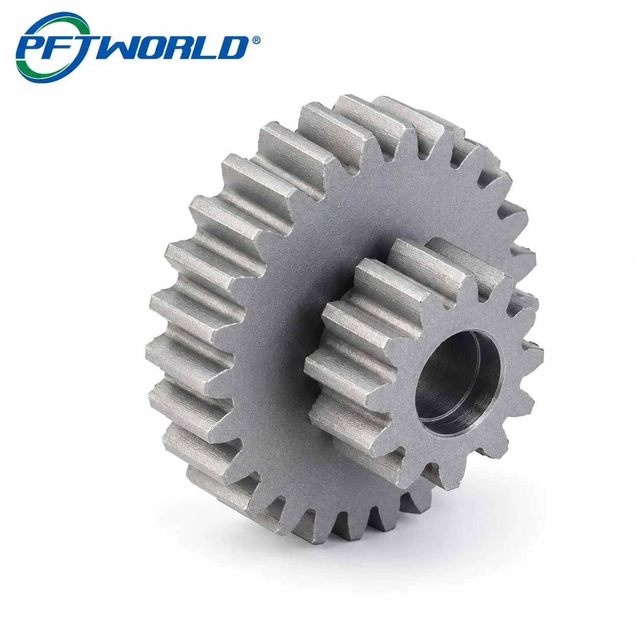
A compound gear — also called a dual-layer or stepped gear — combines two gear profiles of different diameters and tooth counts on a single shaft-mounted body, machined from one solid blank. This configuration lets a gear train change torque and rotational speed at a single mesh point, which is common in gearboxes, robotic actuators, and reduction drive assemblies.
Because both gear layers must share a single bore axis and run true to each other, compound gears demand tighter concentricity and perpendicularity control than single-profile gears. CNC turning establishes the bore and outer diameters, while CNC hobbing or gear milling cuts the tooth profiles on each layer in sequence, referencing the same datum to keep both gear stages in alignment.
02Material Selection for Precision Gear Components
Material choice determines wear resistance, load capacity, and cost-efficiency. The table below summarizes the material families most commonly specified for CNC machined gears.
03Tolerance Control & Manufacturing Process
Gear performance depends on dimensional accuracy at several checkpoints: bore diameter and roundness, tooth profile (involute form), pitch accuracy, and the coaxiality between the two gear layers on a compound part. Typical process flow for a precision compound gear includes:
- CNC turning of the blank — outer diameters, bore, and step faces to a shared datum
- Gear hobbing or wire-EDM gear cutting for each tooth profile layer
- Heat treatment (where specified) for hardness and fatigue life
- Precision grinding of the bore and critical faces to final tolerance
- Dimensional inspection with CMM or gear-specific measuring instruments
Standard achievable tolerances for precision CNC gears typically range from ±0.01mm to ±0.005mm on critical diameters, depending on part size, material, and post-machining processes such as grinding.
04Design for Manufacturability (DFM) Considerations
Engineers reviewing a compound gear drawing before quoting typically check: whether the bore tolerance class is compatible with the shaft fit (clearance, transition, or interference); whether both gear layers can be cut from a single hobbing setup without excessive tool change; and whether the step height between layers leaves sufficient clearance for the hobbing or milling cutter to access the smaller-diameter gear without interference from the larger one.
Flagging these issues during DFM review — rather than after first-article production — reduces tooling rework and shortens the path from drawing to sample delivery.
05Typical Applications
Compound CNC gears are widely used in reduction gearboxes, power tool transmissions, robotics and actuator assemblies, automotive auxiliary drives, and precision instruments where a single component must provide a stepped gear ratio within a compact envelope.
With turning and grinding combined, bore tolerances of ±0.005mm to ±0.01mm are achievable on most precision gear components, depending on material and part geometry.
Alloy steels such as 45# or 40Cr, often carburized or induction-hardened, are generally preferred for high-torque or high-cycle applications due to their fatigue resistance.
The outer profile and bore are typically turned in one setup to keep both layers coaxial; the tooth profiles are then cut (hobbed or milled) referencing the same datum to maintain alignment.
Not always. Heat treatment is specified when the application requires higher surface hardness or fatigue strength; lighter-duty or instrument-grade gears may be used as-machined or after surface finishing only.
Coordinate measuring machines (CMM) verify bore, step, and coaxiality dimensions, while gear-specific instruments check tooth profile, pitch, and runout against the drawing's tolerance class.
Include material grade, tooth module/pitch, bore tolerance class, surface treatment requirements, and the coaxiality tolerance between gear layers — this allows an accurate DFM review and quotation.
Need a Compound Gear Machined to Your Drawing?
Share your gear drawing or specification for a DFM review and tolerance-class quotation from our CNC machining engineering team.
Request a Quote