 EN

Define the mating shape
The open circular cutout and curved channels provide a clear starting point for discussing mating geometry. Specify diameters, radii, clearances and the intended contact surfaces rather than leaving fit to a photograph.

Building 49, Fumin Industrial Park, Pinghu Village, Longgang District
Sunday Closed
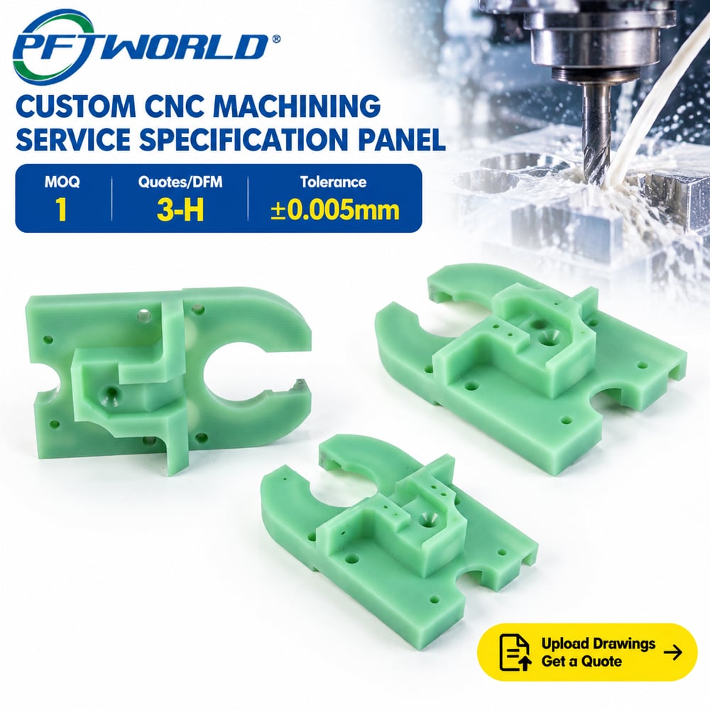
Looking to source a profiled component with curved grooves, stepped faces and multiple holes? Use this photographed part as a starting point for a drawing-based machining enquiry. Specify the material grade, mating features and quantity required for your design.
The sample is identified as green FR4 in the supplied product information. Material grade and machining feasibility are subject to project review.
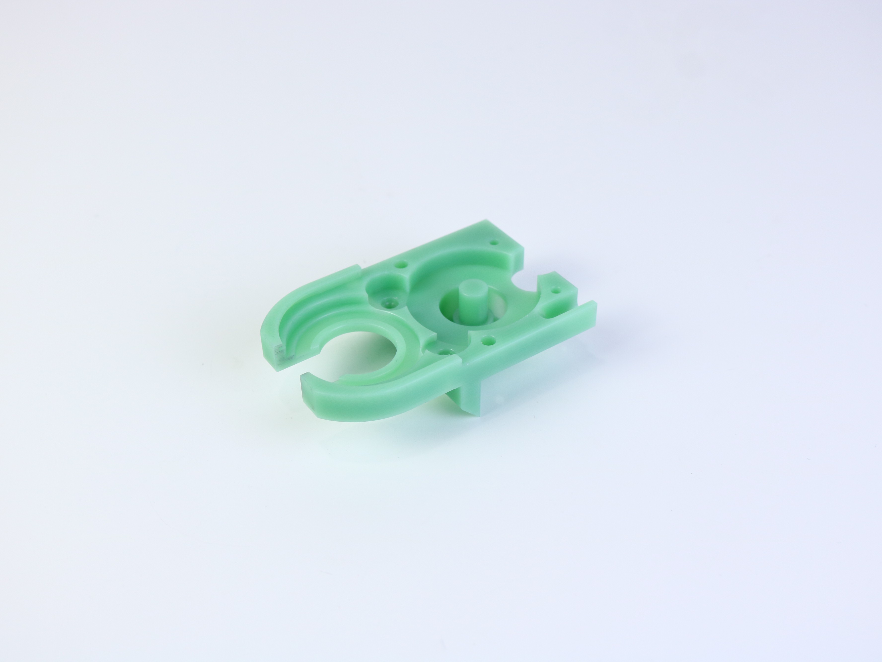
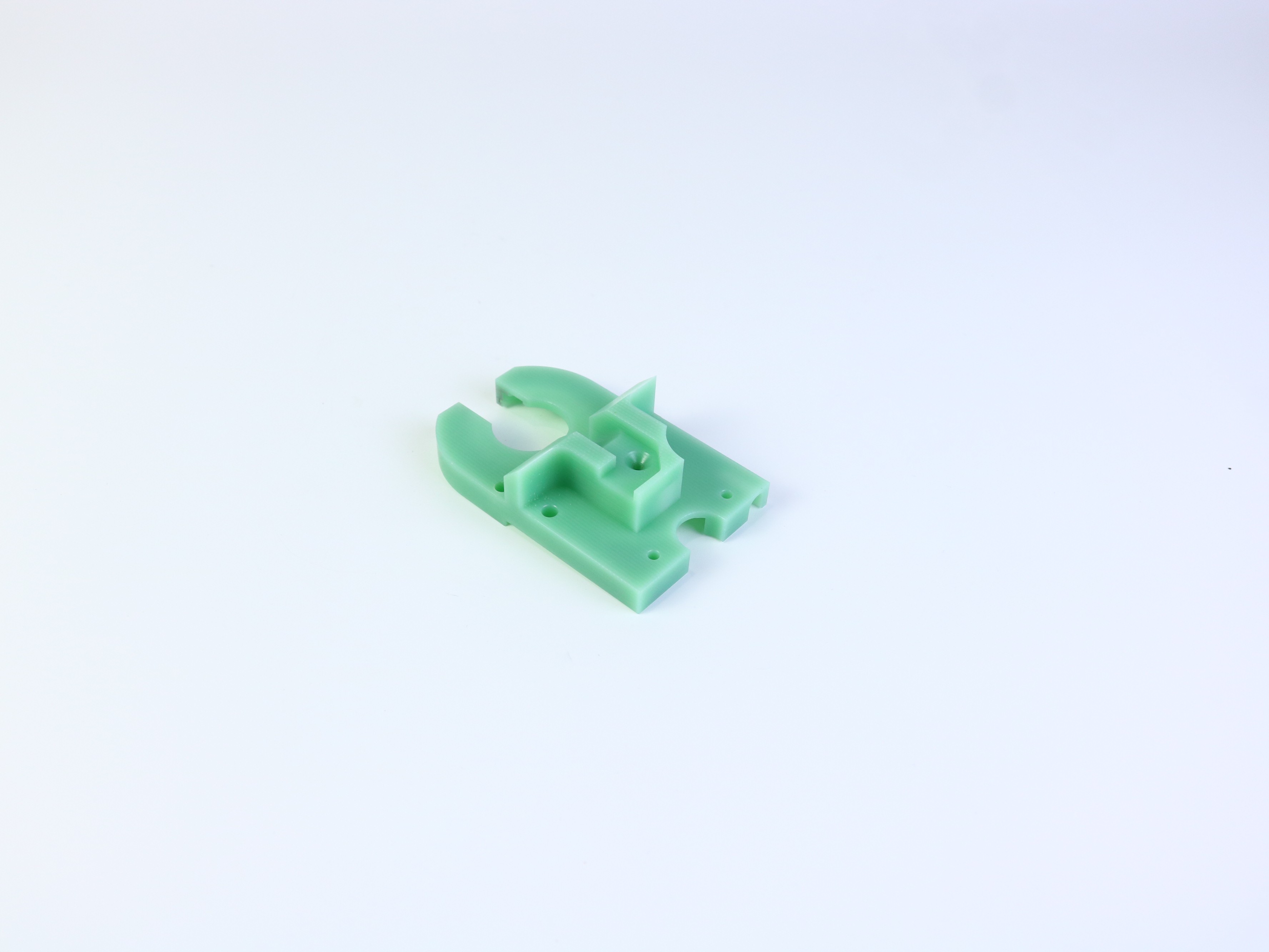
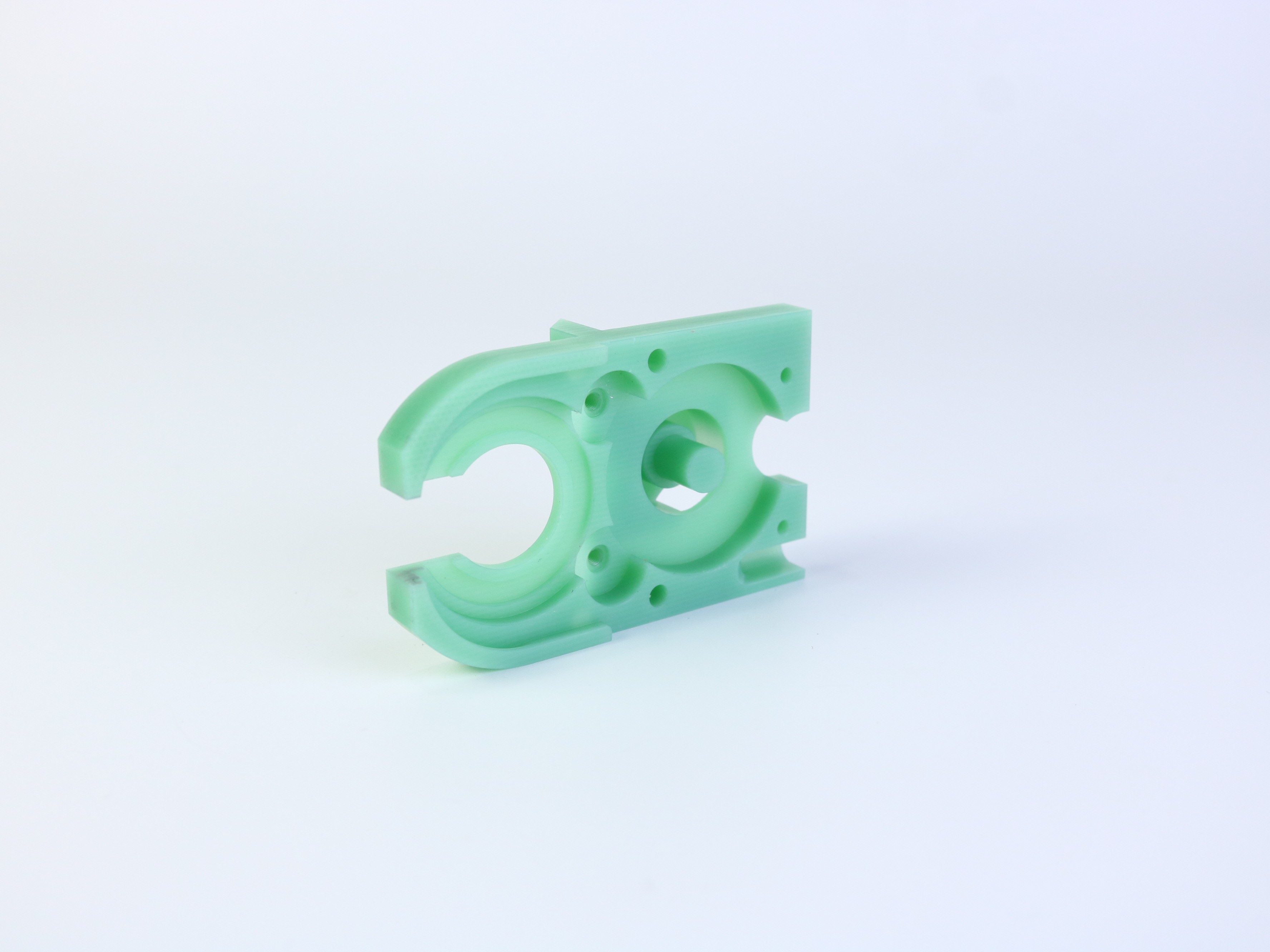
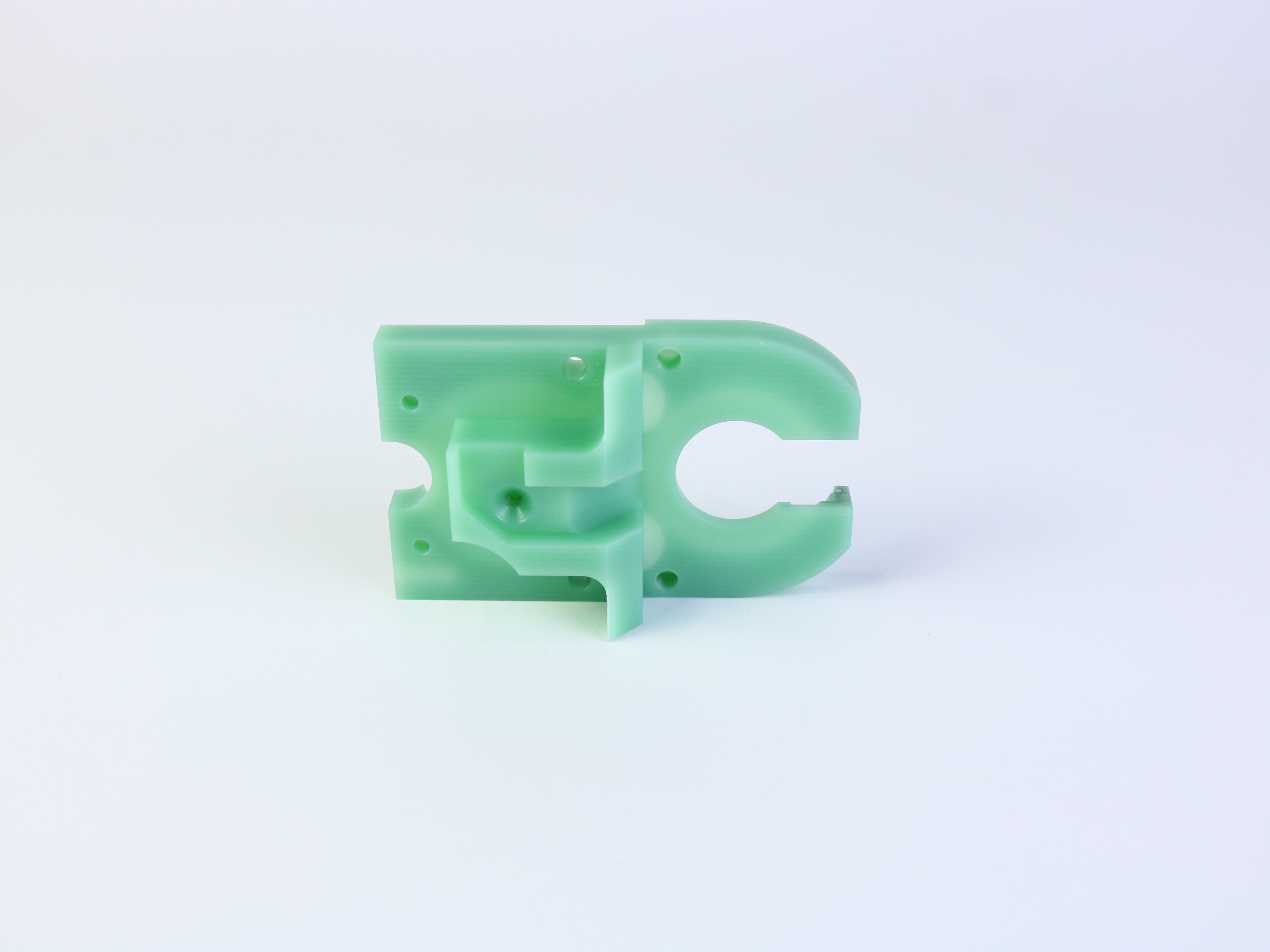
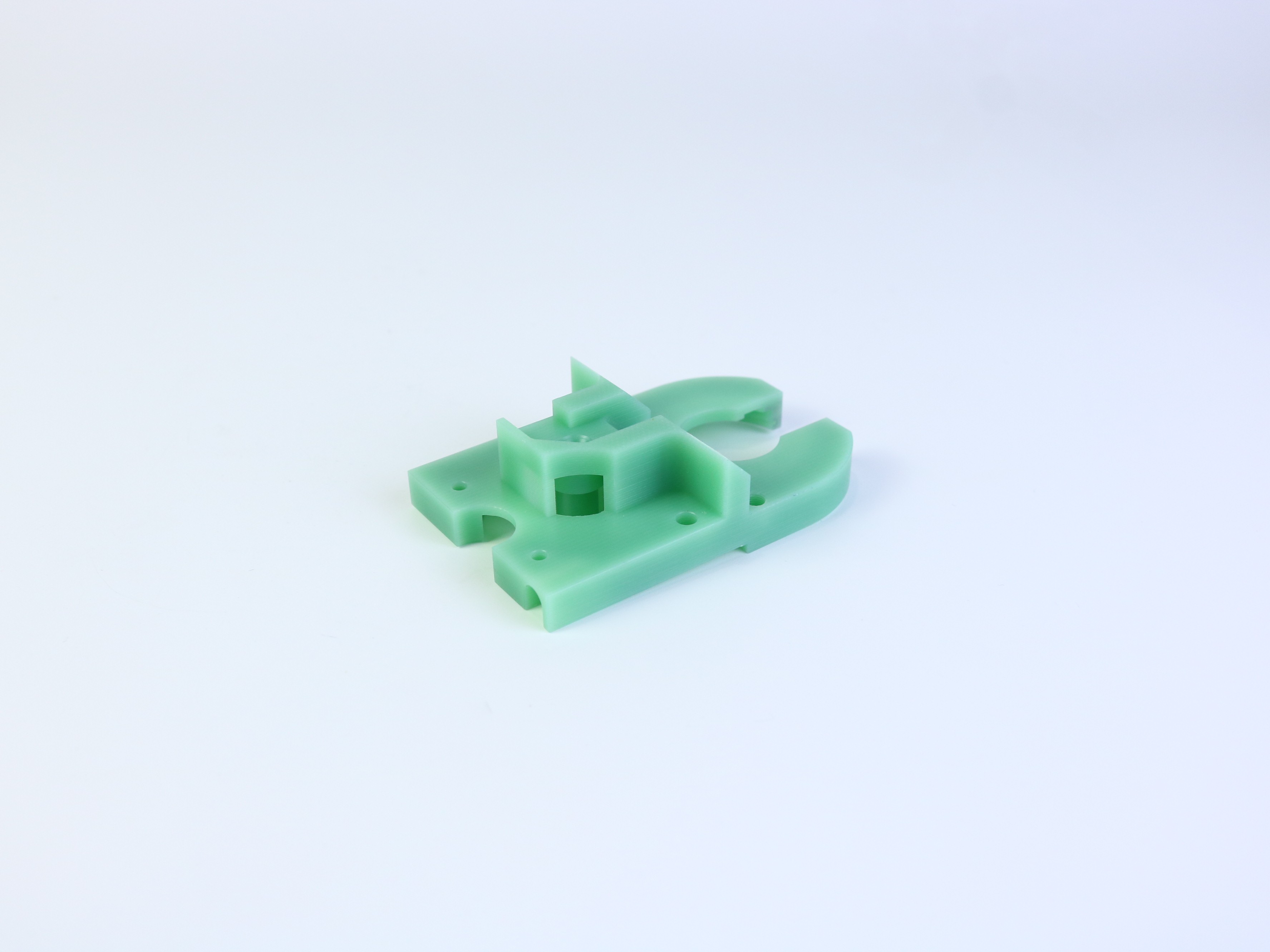
The photographed component has a plate-like body with an open circular cutout, curved channels, recessed areas and several holes. The opposite face shows raised steps and wall-like features. A cylindrical feature is also visible, although its construction and assembly relationship are not established by the photographs.
These details make the relationship between faces, hole locations and mating profiles central to the enquiry. A dimensioned drawing is needed to establish which features locate, support or clear other parts. The images are not a dimensional drawing or evidence of tested performance.
The open circular cutout and curved channels provide a clear starting point for discussing mating geometry. Specify diameters, radii, clearances and the intended contact surfaces rather than leaving fit to a photograph.
Grooved and raised features appear on opposite sides. Identify reference faces and critical step heights so that the machining review addresses their relationship, not just the overall outline.
Several holes are visible, but their function and any threads need a drawing. Define positions, diameters, depths and thread callouts where required to avoid quoting a clearance hole as a fastening feature.
The steps, wall-like sections and recessed geometry call for a feature-level machining review. Identify critical wall thicknesses and internal radii; confirm any proposed geometry changes before production.
FR4 is the supplied material designation, not a complete project specification. Include the required grade and supporting documentation. If the part has an electrical or thermal role, state those requirements separately.
State the acceptance criteria for hole positions, steps, profiles and edges. Agree the required records and inspection method during quotation; photographs alone do not demonstrate compliance.
| Item | Sample information / quotation basis |
|---|---|
| Part type | Profiled component with curved recesses, stepped faces, raised features and multiple holes. |
| Material | Identified as green FR4 in the supplied product information; exact grade and supporting documentation to be confirmed. |
| Colour | Green as photographed. Any colour acceptance requirement should be specified separately. |
| Manufacturing process | Milling identified in the source information; CNC route, setups and additional operations subject to drawing review. |
| Dimensions and tolerances | Subject to drawing review, including datums and critical mating features. |
| Threads and inserts | To be specified where required; not verified from the photographs. |
| Surface roughness and edge condition | Project-dependent. State the required finish and edge acceptance criteria. |
| Surface treatment | To be agreed only if required. No coating or treatment is established by the images. |
| Inspection and documents | Methods, reporting scope and material documentation to be agreed during quotation. |
| Order quantity and production options | Quote-dependent. State prototype, batch or repeat-order requirements. |
| Lead time | Subject to material, geometry, quantity, inspection scope and production review. |
| Drawing files | Provide a dimensioned drawing and a 3D model if available. Confirm accepted file formats through the enquiry channel. |
The sequence below is a project-review framework, not a statement of an established factory process. Confirm the scope, responsible supplier and acceptance documents for each applicable stage in the quotation.
For this geometry, pay particular attention to the relationship between the grooved face, raised face and hole pattern. Specify the mating requirements rather than assuming a general tolerance covers every feature.
The geometry may be relevant to a custom fixture, locating element or profiled support in an equipment assembly. These are possible uses for engineering discussion, not confirmed applications of this sample.
If electrical isolation is part of the design, specify the required operating conditions, material documentation and acceptance tests. The green colour and product designation do not establish an insulation rating, load capacity or approved end use.
The five supplied photographs show the component from several angles, allowing an initial review of its profiles, steps and holes. They do not establish who manufactured it or demonstrate a factory's equipment, certifications or repeat-production capability.
For a qualified sourcing decision, request the production location, relevant equipment information, material records and an inspection plan tied to your drawing. Any prototype, repeat-order or confidentiality arrangement should be confirmed in writing.
The supplied product information identifies the sample as green FR4. The exact grade and material documentation need confirmation; colour alone is not proof of composition or performance.
The images show a profiled component with grooves, steps and holes; they do not show a circuit layout. This enquiry page concerns a custom machined component, while its exact assembly function remains to be defined.
Tolerances are subject to drawing review. Identify the datums, critical hole positions, curved profiles, step heights and mating clearances. No numerical machining tolerance is established by the photographs.
Thread details are not verified from the images. Specify the thread designation, depth and any insert requirement in the drawing where applicable.
Include your preferred order quantity and whether the enquiry is for a prototype, a batch or repeat supply. Availability, minimum quantity and production scope must be confirmed in the quotation.
State the surface and edge requirements, critical dimensions and the records needed for acceptance. Inspection methods, material documentation and any surface treatment should be agreed for the project.
Provide the drawing revision, a 3D model if available, material requirement, quantity, critical dimensions, finish, inspection scope and target delivery date. Confirm accepted file formats with the enquiry contact. Lead time follows project and production review, not the photograph alone.
Confirm the recipient, approved transfer method and any confidentiality agreement before sharing sensitive design files. A confidentiality policy or NDA is not implied by submitting an enquiry.
For a part like this, define how the curved profiles, stepped faces and holes must work together. A drawing-based enquiry makes the material, fit and inspection requirements explicit.
Include the drawing and requirements above in your machining enquiry. Confirm the material, process and inspection scope before accepting a quotation.
Discuss Your ProjectDescribe what the component must locate, support or clear, and identify the mating surfaces. Confirm which features are fixed and which can be reviewed for manufacturability.
Before sending files, confirm the enquiry contact, accepted formats and transfer method. This page does not collect or transmit drawings.
Copyright © Shenzhen Perfect Precision Products Co., Ltd. All Rights Reserved — Privacy Policy — Blog