 EN
EN


Clevis Bracket Machining: Why Does the Pin Sit at an Angle?
Clevis bracket machining is the kind of job where every dimension in the inspection report can be inside tolerance and the linkage still will not work.
Job 260414004 arrived in August 2023 from a maker of clevis and mounting components whose previous shop had shipped brackets that were, on paper, correct. The pin went into the fork by hand, the two holes in the base lined up with the frame, the base sat flat, and yet the linkage pulled to one side through its stroke and the pin wore a bright band on one edge of the bore within a few weeks of service.
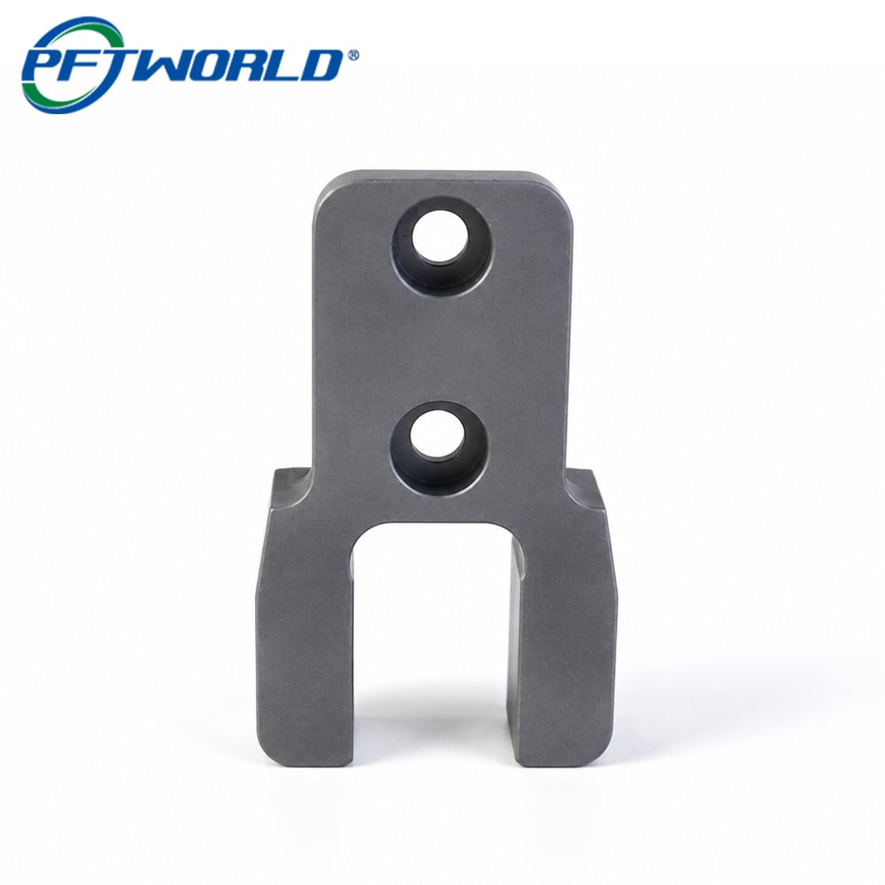
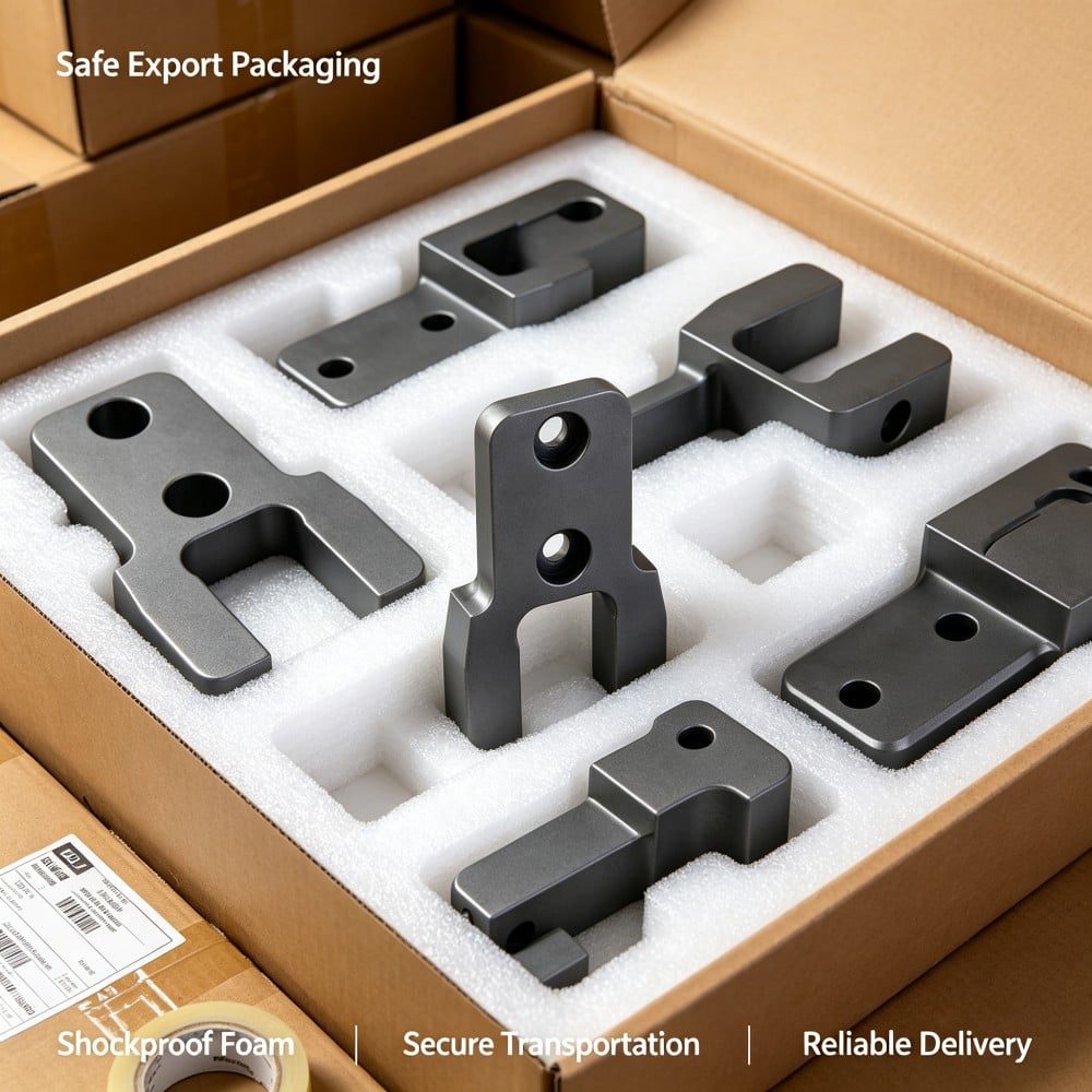
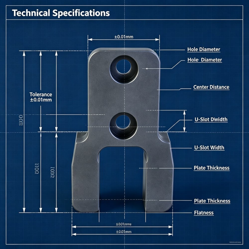
The parts in the photographs are the production run that followed: a 1Cr17Ni2 martensitic stainless clevis bracket roughly 72 mm long, quenched and tempered, with a thick forked end carrying two prongs and a deep U slot, a shallower pocket worked into the fork face, and a thinner rectangular base plate about 24 mm wide with two counterbored mounting holes at roughly 25 mm spacing. The dark charcoal-grey matte surface is the heat-treated finish.
What this bracket has to do?
Three jobs, and they only work together.
The base plate mounts. Its underside is the mounting face, and the two counterbored holes fix the bracket to a frame. The bolt heads have to sit below the face so nothing stands proud, and the plate has to sit flat so the bracket does not rock when it is tightened down.
The fork takes the pin. The two prongs carry a bore each, and the pin passes through both, so the two bores have to share one axis. Around the bore, the U slot and the pocket define where the mating component sits and how much it can move.
The bracket holds an angle. This is the job that never appears on a single dimension: the pin has to sit square to the mounting face. If it does not, the linkage travels on a skew, the pin loads one edge of the bore, and the wear shows up somewhere the bracket was never blamed.

Why every feature can pass and the assembly still fail?
Each feature is checked against itself
A bore has a diameter and a position. A pocket has a depth. A plate has a thickness and a flatness. A prong has a thickness and a parallelism to its neighbour. Every one of those is measurable on its own, and on this bracket every one of them was measured and passed.
That is the catch in the inspection report. A report built from feature checks describes a collection of features, not a working bracket.
The relationships between features are what the assembly uses
The pin does not care how round either bore is in isolation. It cares whether the two bores share an axis, and whether that axis stands square to the face the bracket is bolted against. The mating component does not care about the pocket depth on its own; it cares whether the pocket floor is parallel to the face the bracket mounts on, because that parallelism is what keeps it seated through the travel.
None of those relationships appear as a line on a conventional inspection sheet. They are the difference between a bracket that passes and a bracket that works, and they are the requirements heat treatment is most likely to spoil.
The mounting face is the reference the customer actually uses
When the linkage is assembled, the bracket is bolted down, and from that moment every relationship in the assembly is defined by the mounting face. It is the primary datum whether or not the drawing says so.
So the mounting face is the reference the bracket has to be built and measured from. A bracket that was machined and checked from its fork, or from the outer edges of the base plate, has been built from references the customer never touches, and the difference between those references and the mounting face is where the bend in the linkage comes from.
The two relationships heat treatment spoils
The pin axis and the mounting face
The pin bores are cut while the material is free cutting, which on a bracket like this means before the cycle. The bores come out round, on position in the fork, and square to the surfaces the machine was set against at the time.
Then the bracket is quenched and tempered. The base plate and the fork are very different sections of the same part: the fork is thick, the base is thin, and the two respond to the thermal cycle at different rates. The base plate moves more than the fork does, and the fork's relationship to the base plate is exactly what sets the pin axis relative to the mounting face.
The result is a bracket where both bores are still round and still the right size, the base still sits flat, and the pin axis has picked up an angle to the mounting face. Nothing in the report changed. The assembly did.
The pocket floor and the prong faces
The pocket in the fork face is shallow, and its job is to control where the mating component sits and how far it can move. Its depth matters, but on this bracket so does its parallelism to the mounting face, because a pocket floor that tilts moves the mating component with it.
The pocket is cut before the cycle like the rest of the fork, so the same movement that tilts the pin axis also tilts the pocket floor. A pocket that is the right depth at its centre and shallow on one side will seat the mating component on one edge, and the fitter will describe it as loose rather than as tilted, which sends the investigation in the wrong direction.
How the brackets were made, step by step?
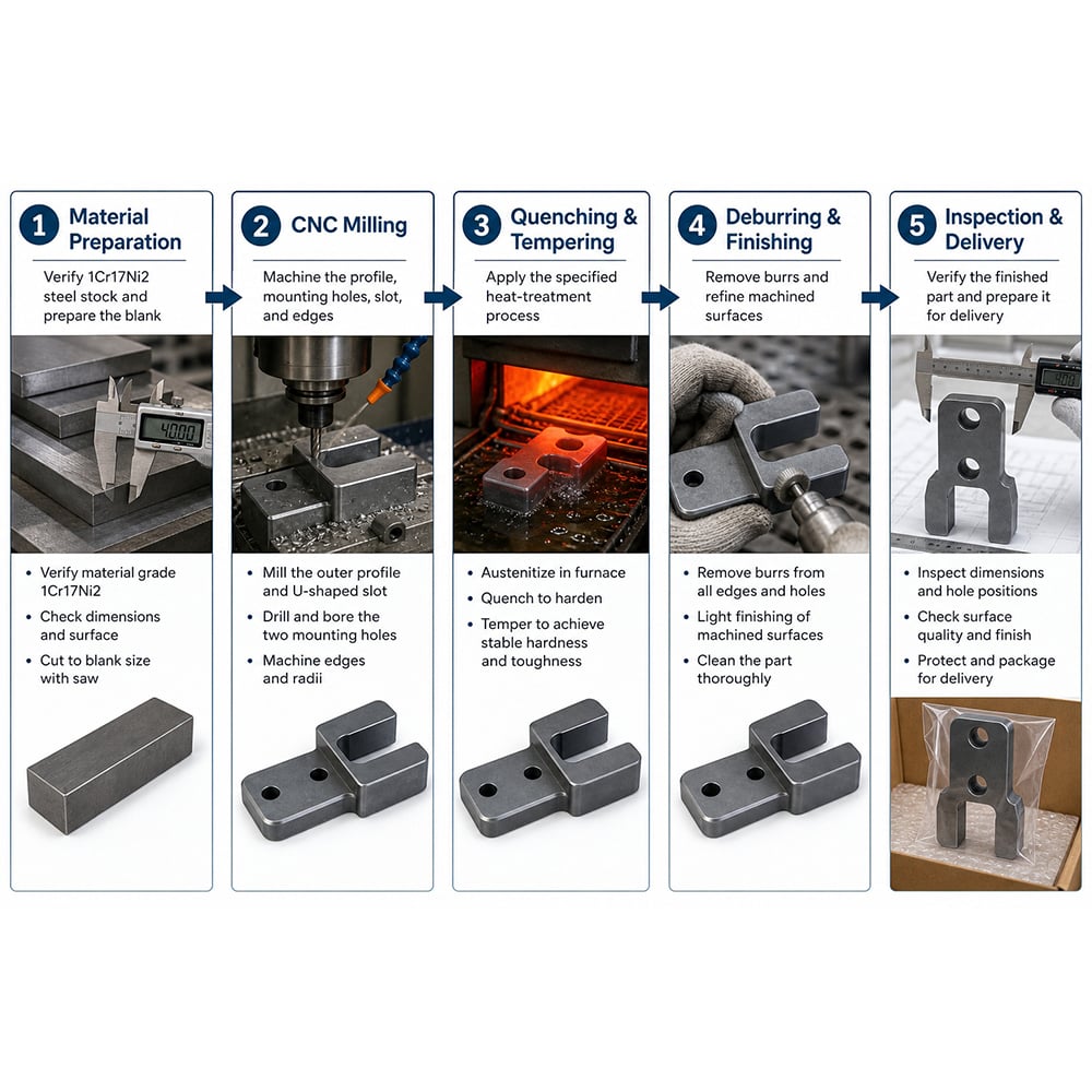
Step 1 - Rough the bracket and leave stock on the reference faces
The bracket is roughed from 1Cr17Ni2 bar, with the outline, the fork and the base brought close to size but a deliberate allowance left on the base plate faces and on the fork's outer faces. Those are the faces the part will be referenced from later, and they have to be cut after the cycle rather than before it.
Step 2 - Quench and temper to the drawing's hardness
The rough bracket goes through the full quench and temper cycle to the hardness the drawing calls for, which is what gives the fork its wear resistance and stops the bore edge deforming under the pin. This is the largest movement the bracket will see, and everything that follows is planned around that.
Step 3 - Face the mounting face and the prong faces in one setup
The mounting face and the fork's outer faces are faced after the cycle, in one setup, so the relationship between them is produced by a single cut rather than inherited from before the heat treatment. This is the step that puts the bracket's own reference back where the customer's assembly expects it.
Step 4 - Bring the base plate to thickness from the mounting face
The base plate is brought to the drawing's thickness measured from the mounting face, so the step at the transition to the fork sits where the drawing puts it. Measuring the thickness from the other side would leave the step correct and the mounting face wrong, which is the opposite of what the assembly needs.
Step 5 - Cut the pocket floor parallel to the mounting face
The pocket is finish cut now, with the bracket sitting on the faced mounting face, so the pocket floor comes out parallel to the face the bracket bolts against. Depth is checked at more than one point across the floor, since a floor that is correct at its centre and shallow at one edge is the failure that reads as a loose fit.
Step 6 - Bore and ream the two prong holes from the mounting face
The two prong holes are bored and reamed after the cycle, working from the mounting face so the pin axis is set square to the face the customer bolts against rather than square to the fork's own surfaces. Where the setup allows, both holes are finished in one operation so their axes are common by construction rather than by two separate set-ups.
Step 7 - Cut the counterbores from the same face
The counterbores are cut from the mounting face so their depth references that face and the bolt heads sit below it. Cutting them from the far side is the mistake that produces a counterbore that measures correct in depth and still leaves a bolt head proud of the face the bracket sits on.
Step 8 - Deburr the slot corners and check the bracket as an assembly
Every chamfered edge and the corners of the U slot are deburred, with the slot corners given particular attention because they are a stress concentration in a martensitic stainless. Final inspection includes the individual features, but it is released on the assembly checks: a pin through both prong holes with a square stood on the mounting face, the pocket floor checked for parallelism to that face, and the bracket bolted down and swept through its travel.
What the 2,000-piece run measured?
| Check | Specification | Held across 2,000 brackets |
|---|---|---|
| Mounting face and prong faces | Faced after the cycle, in one setup | One setup for both, so the relationship came from a single cut |
| Base plate thickness | To drawing, measured from the mounting face | Step sat where the drawing puts it |
| To drawing depth, parallel to the mounting face | Depth checked at more than one point across the floor | |
| Prong holes | On position, axes common | Bored and reamed from the mounting face after the cycle |
| Pin axis to mounting face | Square to the mounting face | Checked with a pin and a square on the mounting face |
| Counterbores | To drawing depth, bolt heads below the face | Cut from the mounting face |
| U slot | To drawing width and depth | Slot corners deburred |
| Hardness | Drawing range, even | Quenched and tempered on a controlled cycle |
| Edges | Deburred and chamfered | Nothing sheds or cuts at assembly |
Two thousand brackets shipped in 18 days, and the customer reported that the pins sat square, the linkage ran true through its travel, the bolt heads sat below the mounting face, and the bracket stopped wearing one edge of the bore.
The fault we found in our own trial run
Our trial brackets passed everything we measured, and the customer's assembly rejected them.
The trial report was clean: both prong bores were round and on position, the base was flat, the counterbores were to depth, the pocket was to depth, and the pin went through both prongs by hand. What none of those checks described was the angle between the pin axis and the mounting face. When a pin was pushed through the trial brackets and a square stood on the mounting face, the pin leaned, and once the bracket was bolted down the linkage bound part way through its travel.
Three changes went into production. The mounting face and the fork's outer faces were faced in one setup after the cycle instead of being inherited from the soft state. The prong bores were bored and reamed from the mounting face as the working datum rather than from the fork's own surfaces. And the release criterion was changed to an assembly check: a pin through both bores with a square on the mounting face, plus the bracket bolted down and swept through its travel, with the individual feature measurements kept as process control rather than as the thing that decides whether a batch ships.
Between the trial and production the skew complaint disappeared, and the bore edge wear the customer had been seeing at three weeks stopped appearing.
Three ways to reference a clevis bracket, compared
| Reference used for the bores | How the pin axis is set | Risk of skew to the mounting face | Where it fits |
|---|---|---|---|
| Mounting face, after the cycle | Both bores finished from the faced mounting face, ideally in one operation | Lowest, because the bore axis and the customer's datum come from the same surface | Brackets and forks where the pin has to be square to a mounting surface, the route used here |
| Fork outer faces, after the cycle | The bores are squared to the fork itself | Medium: correct if the fork happens to be square to the mounting face, and the two are not checked against each other | Parts where the fork geometry is the functional reference and the mounting face is incidental |
| Fork outer faces, before the cycle | Both the bores and the fork are cut in the soft state and the cycle comes last | Highest, because the relationship between fork and base is the one the cycle changes most | Simple brackets with heavy bases and little difference between section sizes |
The third row is the route that produces a clean inspection report and a skewed assembly, and it is the route most brackets are quoted on. The choice is worth making explicitly, because the cost of the first row is one extra setup and the cost of the third is a batch that has to be scrapped at the customer's bench.
FAQ
Why does the pin sit at an angle even though both bores are on position?
Because bore position and bore alignment are different requirements, and so is the angle of the bore axis to the face the bracket mounts against. Each prong bore can be perfectly round and perfectly placed within its own prong while the two bores no longer share an axis, or while that axis no longer stands square to the mounting face. Those relationships are not on a conventional inspection sheet, and heat treatment is what breaks them.
Which face should a clevis bracket be machined and measured from?
The mounting face, because that is the surface the customer bolts against and the reference every relationship in the assembly is taken from once the bracket is installed. Machining and checking from the fork, or from the outer edges of the base plate, means the bracket has been built from references the assembly never uses, and the difference between those references and the mounting face is where a skew comes from.
Does the pocket depth matter if the mating part still fits?
The depth matters and the parallelism of the pocket floor matters more, because a floor that is the right depth at its centre and shallow at one edge seats the mating component on one edge only. In service that reads as a loose fit rather than as a tilted one, so the complaint tends to be investigated as a size problem when the real cause is that the floor is not parallel to the mounting face.
How should a clevis bracket be checked before shipping?
In the assembled condition rather than only as features: a pin through both prong holes with a square stood on the mounting face to check the axis, the pocket floor checked for parallelism to that face, the counterbores checked from that face, and the bracket bolted down and swept through its travel. Feature measurements belong in the process log; the assembly checks are what should decide whether a batch ships.
What to put on your drawing?
Six lines keep a clevis bracket from passing inspection and failing the linkage:
1. Name the mounting face as the primary datum, and say that the prong bores are square to it.
2. Give the two prong bores as a coaxial requirement, not as two independent positions, so the two are checked as one axis.
3. Give the pocket depth with a tolerance and state that the pocket floor is parallel to the mounting face.
4. Give the base plate thickness measured from the mounting face, and say which side the step is to be taken from.
5. State the counterbore depth from the mounting face, and say that the fastener heads are to sit below that face.
6. Say whether the slot corners carry a radius and what that radius is, since an internal corner in a quenched and tempered martensitic stainless is where a crack starts.
A clevis bracket is not difficult to machine feature by feature. It is difficult to hold together in the relationships that the assembly actually uses, and those relationships are the ones the heat treatment moves most. Put the mounting face first, finish the fork from it after the cycle, and check the bracket as an assembly rather than as a list of dimensions.