 EN
EN


Overmolded POM Gear Brass Insert: Why Do Hubs Come Loose?
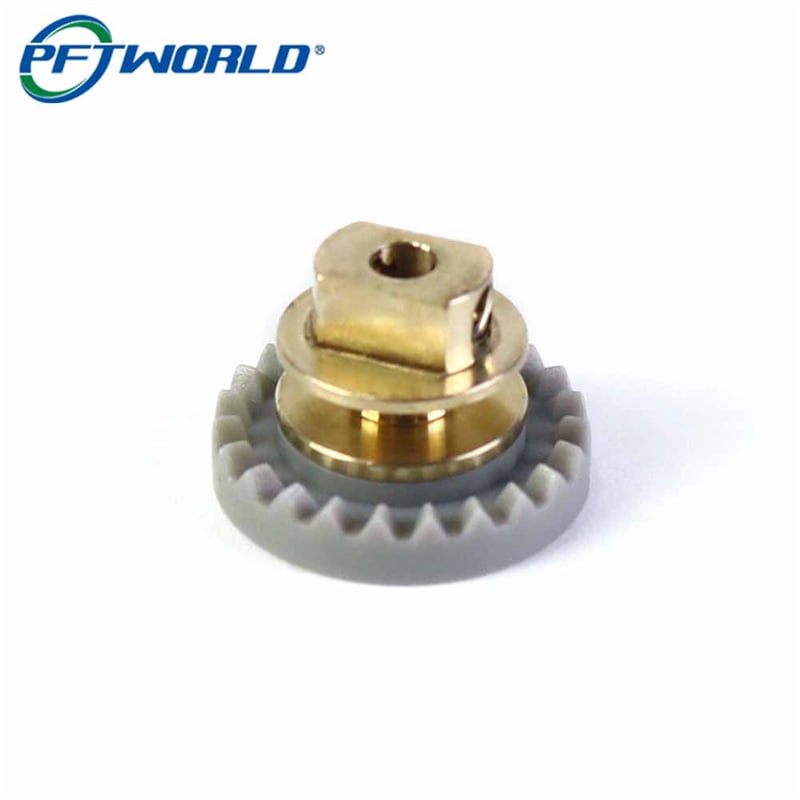
A gray POM gear with a turned brass core looks like a simple composite, and that is exactly why so many of them fail. Job 260626003 arrived in June 2025 from an office equipment maker whose earlier supplier had shipped a batch of overmolded POM gears that passed every dock inspection and then lost their inserts inside the machine: some spun on the shaft under reversing torque, some split the molded rim during assembly, and some drifted so far off center that the drive ran loud and the set screws would not hold.
What follows is what we changed, the numbers we measured across the run, and the fault we found in our own first fifty parts. If you are buying an overmolded POM gear with a brass insert, the retention section is the one worth your time, because the obvious answer, pressing the insert in tight and trusting friction, is the reason the first batch failed.
What the metal core is actually for
The two materials are doing two different jobs, and that split is what makes the part work.
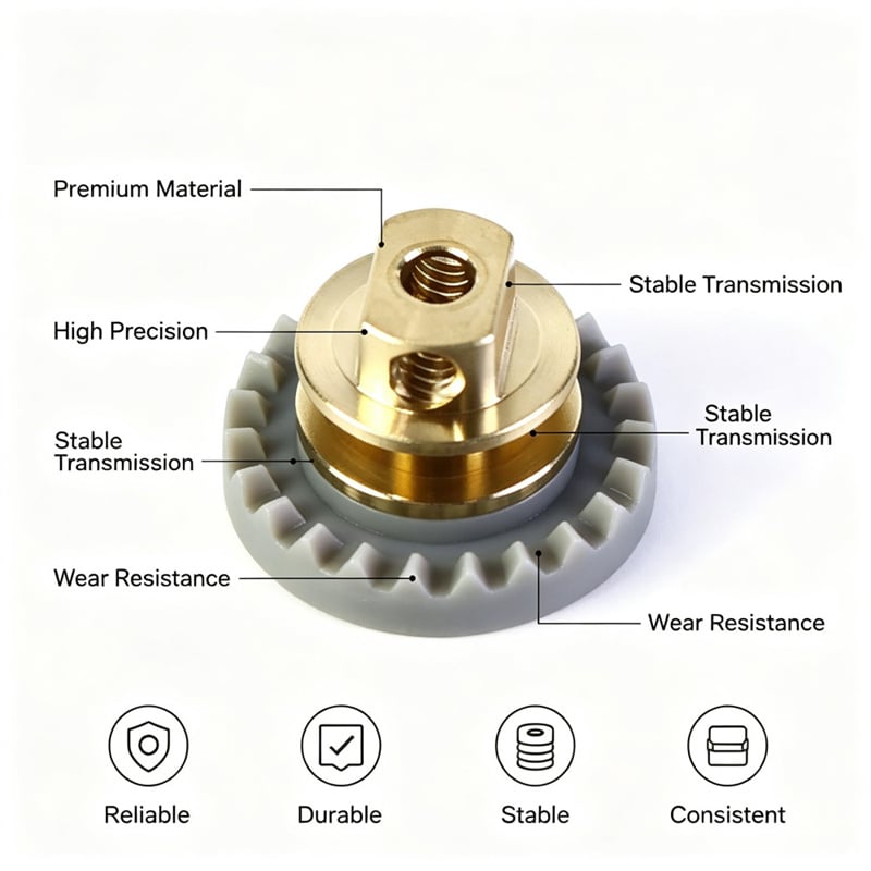
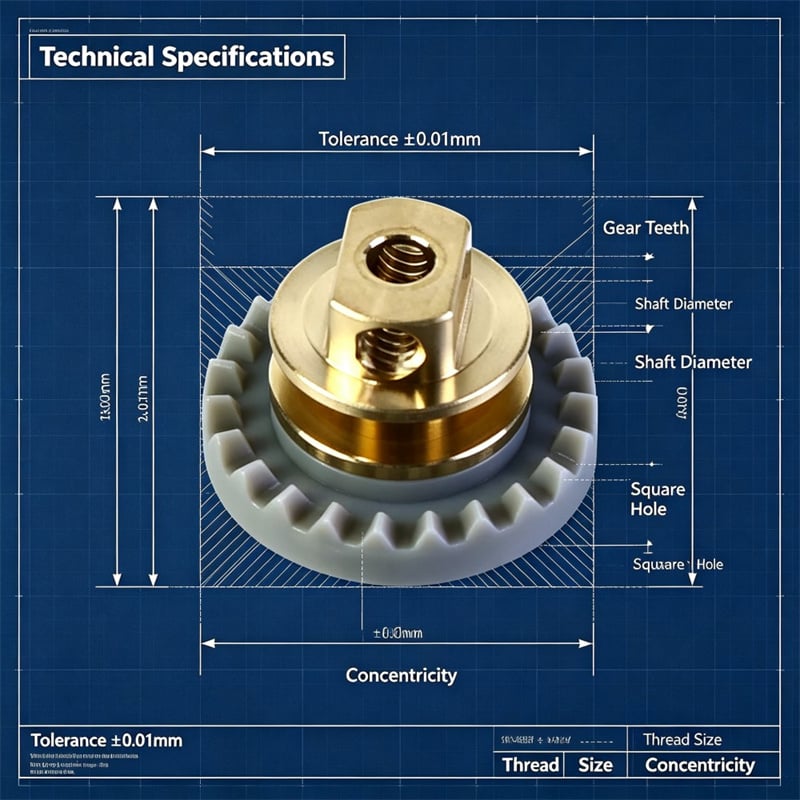
The molded POM body carries the tooth geometry. POM is stiff, dimensionally stable under load, and slick enough that a small gear pair runs quietly without grease. The brass core carries everything that takes point load: the central bore that locates the shaft, the two flats machined on the top end that hand drive torque to a mating part, and the tapped cross holes that lock the assembly to the shaft with set screws.
Molding the teeth onto a machined core, rather than machining the whole gear from brass or steel, buys quiet running, lower weight and no lubrication, and it costs less than a fully machined part at volume. The trade is this: the joint between plastic and metal is now a load path, and it has to be designed, not assumed.
The failure mode nobody measures
POM keeps moving after the molding machine stops
POM crystallizes as it cools and shrinks about 1.8 percent from the cavity. It also keeps relaxing for hours after the part leaves the mold, and it moves roughly five to six times more than brass over the same temperature change. A fit that measures tight on the bench in the morning can measure loose in a warm housing in the afternoon, without anything having been touched.
That is the whole problem in one sentence: a friction joint between two materials that expand at different rates is a joint with an expiry date.
The rim is the weakest ring in the part
Pressing a smooth collar into a molded hub loads the surrounding plastic in hoop tension. The thinnest, coldest and most stressed ring in the whole part is the rim around the hub, and it is also where the runner gate and the parting line usually sit. When the press fit is dimensioned for tightness rather than for fit, the rim is what pays for it, which is how you get a gear that cracked on the assembly bench and never even reached the machine.
The joint is asked to do two jobs at once
Location and drive are not the same requirement. A hub insert has to stay concentric to the gear axis to a few hundredths of a millimeter, and it has to resist reversing torque without any rotation at all. A friction fit does the first job reasonably well when it is fresh and the second job poorly forever, because the normal force it depends on is the first thing to go when the plastic relaxes.
Three ways to hold a brass insert, and when each one works
| Method | How it holds | Torque resistance | Concentricity | Where it fits |
| Press fit on a smooth collar | Friction only, from interference between collar and hub | Low to medium; decays as POM relaxes and warms | Good only if the hub is cut after molding | Low-torque location, light duty, prototypes |
| Knurled collar pressed to a controlled depth | Form lock: the knurl teeth bite into the plastic and torque travels through the teeth | High, holds under reversing load | 0.02 mm, when the hub is cut after the body settles | Drive gears, shafts with set screw locking |
| Insert placed in the cavity and molded in place | Polymer shrinks onto the knurl as it cools | High | Depends on tool location of the insert | High volume, one insert geometry, fixed orientation |
For this job we ran the middle option, and the reason is in the first row: friction is a force you have to keep, form is a shape you already have. A knurl that has bitten into POM keeps transmitting torque even after the plastic has relaxed and the interference is gone.
How this gear was built, step by step
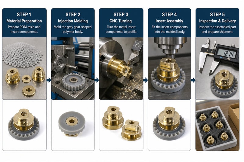
Step 1 - Mold the body in POM, to the drawing's gray
The tooth cavity and hub are cut so the hub comes out slightly undersize, leaving stock for a later turning operation. Color is set with a masterbatch against a Pantone Cool Gray 7C sample, which matters more than most buyers expect, because gray is where batch drift shows first.
Step 2 - Let the molded body settle for 24 hours
The parts rest for a full day before any finish cut. Cutting the hub while the part is still relaxing means the fit will change after it has been cut, and the measurement you took at the machine will no longer describe the part you ship.
Step 3 - Turn the brass insert in one setup
The insert is turned complete in a single setup: the central bore, the two flats on the drive end, the locating flange, the neck and the knurled collar. One setup keeps the flats, the bore and the collar sharing a single axis, which is what makes the assembly concentric later. A second setup is how you end up with a core that fits the shaft perfectly and sits crooked in the gear.
Step 4 - Cut the hub to its final fit
After settling, the hub is turned to the interference the press needs. This is the step that separates this process from the one that failed: the fit is cut in stable plastic, not in plastic that is still shrinking.
Step 5 - Press on a heated press, to a controlled depth
The insert goes in on a heated press inside a 1.2 to 1.6 kN force window, seated to a fixed depth set by the flange. Depth, not force alone, is the control: force tells you the joint is tight, depth tells you the flange is home and the core is square to the gear face.
Step 6 - Tap the cross holes after the press
The two set screw holes are tapped after the insert is seated, so the thread is cut in the part's final position rather than in an insert that will move a few hundredths of a millimeter afterwards. A thread tapped before pressing is a thread that can end up out of square.
Step 7 - Inspect the joint, not only the dimensions
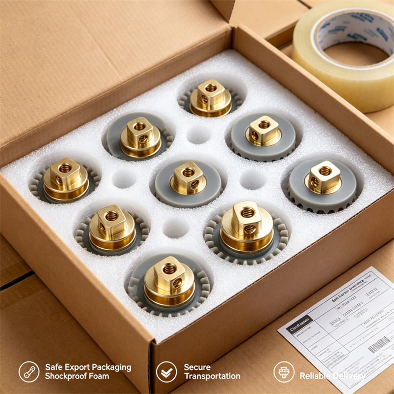
Inspection covers insert concentricity, axial pull-out on a destructive sample, torque at the hub through reverse cycles, tooth form, and a visual check for any crack at the rim. Parts are then packed so the molded teeth do not touch each other in the box.
The first fifty pieces, and the fault we found
The trial run of fifty gears failed, and the failure was ours, not the material's.
Twelve parts came out of the press with a hairline crack at the rim. We had pressed the first batch with the hub cut to nominal, directly after molding, without the settle step. The rest of the trial group, pressed after a full day of rest, showed no cracking at all. The difference was not luck: the unhoused parts were still shrinking when the collar went in, so the interference was effectively higher than the drawing said by the time the press reached the flange.
Two changes went into production. First, no insert is pressed into a body less than 24 hours old, and the age is recorded on the traveler. Second, the press fixture seats the insert on a hard stop at the flange instead of running to a force limit, so a body that has drawn slightly tighter than expected cannot be overloaded to reach the number.
The knurl was also shortened slightly in the molded zone so that it engages the plastic in the upper hub only and never touches the flash-prone area near the parting line, where a bitten-in tooth would start a split. Between trial and production the crack category disappeared completely.
What the 15,000-piece run measured
| Check | Drawing spec | Held across the run |
| Insert concentricity to the gear axis | 0.02 mm | Inside the band on every part after pressing |
| Axial pull-out of the insert | At least 900 N | No part below the limit in the destructive sample |
| Torque at the hub | 2.5 N`m through 50 reversing cycles | No rotation at the knurl |
| Press seating force | 1.2 to 1.6 kN window | Held inside the window, depth set on the flange stop |
| Gear body | 24 teeth, bore and flats to one axis | Tooth form and axis checked at first article each shift |
| Molded teeth | No crack, no flash at the mesh | Zero cracked rims at final inspection |
| Color | Pantone Cool Gray 7C | Gray matched batch to batch against the approved sample |
Fifteen thousand gears shipped in 21 days, and the first assembled drives ran quiet on the customer's line with no insert movement reported.
Color is a tolerance too, especially in gray
Mid grays are unforgiving. A shift of a couple of units in lightness reads as a different material to a buyer holding two parts side by side, and it reads as a different product to a customer opening a service kit six months later. Three habits keep it stable: one masterbatch lot per order when quantity allows, a retained approved sample kept in a dark drawer rather than on a bench in daylight, and a color reading against that sample at the start and the end of every molding shift, not only at the first article.
What drives the cost of an insert-molded gear
Four items decide the price, and only one of them is the plastic:
·The mold. Cavity count, tooth form and whether the hub needs a solid instead of a core pin. This is the largest single number and it is paid once.
·The turned insert. Flats, flange, knurl and a bore that must share one axis. A single-setup insert costs more per part than a two-operation one and saves more than it costs.
·The settle and the second cut. You are paying for a day of shelf time and a finishing pass that exists only because POM moves.
·Inspection depth. Pull-out and torque testing are destructive, so the price includes sampling rather than 100 percent testing, and the sample size is worth agreeing in writing.
Ask any supplier what their settle time is and how the press is controlled, depth or force. The answer tells you whether the joint was designed or hoped for.
FAQ
Does an overmolded POM gear need a knurled insert?
Only if the joint has to transmit torque. Knurling converts the joint from friction into form, so torque travels through the teeth of the knurl instead of through interface pressure that fades as the plastic relaxes. For a part that only has to locate a shaft with no drive load, a smooth collar with a correct fit can be enough.
Can the insert be pressed in after molding instead of molded in place?
Yes, and pressing after molding is often the better route when the insert has flats or a bore that must stay aligned, because the hub can be cut after the body settles and the insert can be turned in one setup. Insert molding suits high volume with one fixed geometry, where the tool can locate the core and the shrink works in your favor.
Why do brass inserts crack the plastic rim?
Because the press fit is dimensioned for tightness rather than for fit, and because the part is often still shrinking when the insert goes in. The rim around the hub is the thinnest ring in the part and the place where the gate and parting line meet, so it takes the hoop stress first. Settling the body and controlling depth instead of force removes both causes.
How do you check insert retention without destroying good parts?
You do not, for the pull-out number. You section a sample to confirm the knurl engagement, pull a sample to failure to prove the margin, and cycle a sample at working torque to prove the joint does not rotate. Production parts are then controlled by the press parameters and by concentricity, which can be measured without damage.
What to put on your drawing
Most of the arguments in this article are settled by five lines on a drawing:
1. State the insert material and the plastic, including the color reference and the accepted color difference.
2. Give the insert concentricity to the gear axis as a real tolerance, not as a note.
3. Give the axial retention as a minimum force, and say whether it is verified by sample or by calculation.
4. Specify how the torque is transmitted: flats, splines or knurl, and where the knurl is allowed to sit.
5. Say whether the insert is pressed after molding or placed in the cavity, and if you have no preference, say so and let the process decide.
Joining metal to a moving polymer is not a detail that can be left to a default tolerance. Get the joint right and the rest of the gear is ordinary work: quiet teeth, a true axis, and a gray that still matches the sample a year from now.