 EN


CNC Machined Precision Gear Shafts: Material, Tolerance & Design Guide
CNC Machined Precision Gear Shafts: Material, Tolerance & Design Guide
What engineers and sourcing teams need to know about material selection, tooth accuracy, tolerance control and FAQs before specifying a custom gear shaft.
Why Gear Shaft Quality Matters
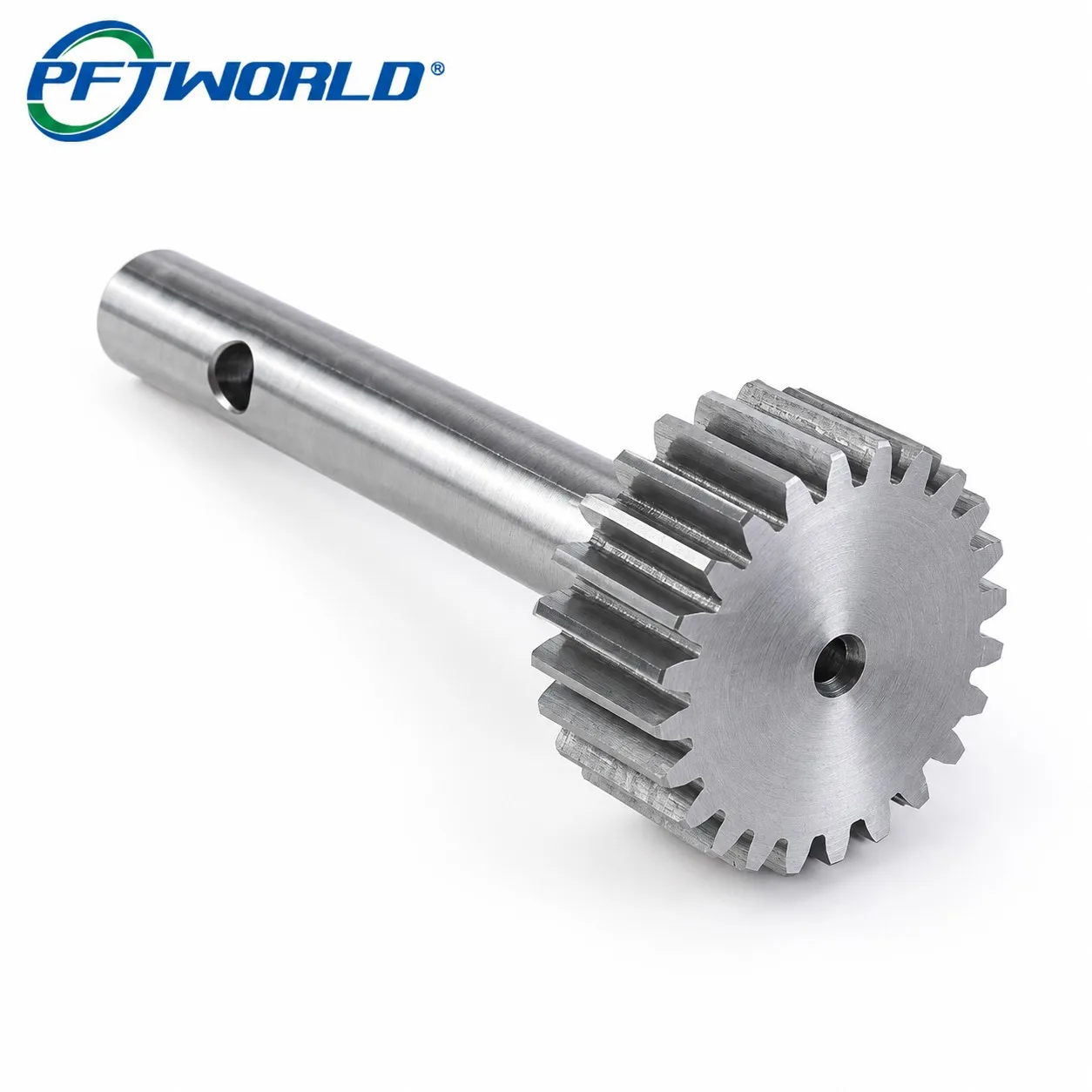
The part pictured above — a CNC-machined spur gear integrated with a keyed shaft — is a core transmission component in gearboxes, robotics, and automation equipment. Unlike stamped or cast gears, CNC-machined gear shafts deliver tight tooth-profile accuracy, consistent concentricity between the gear bore and shaft axis, and the dimensional repeatability required for smooth, low-noise meshing under continuous load.
This guide breaks down the material, tolerance, and manufacturing factors that determine gear shaft performance, followed by the questions engineers and buyers ask most often during sourcing.
Material Selection for Gear Shafts
Material choice is driven by load, environment, and weight constraints. Carbon and alloy steels (45#, 40Cr, 20CrMnTi) are the default choice for medium-to-high torque applications because they accept carburizing and quenching, which hardens the tooth surface while keeping the core tough. Stainless steel (303/304) trades some wear resistance for corrosion resistance, making it suitable for food, medical, or outdoor equipment. Aluminum alloys such as 7075 are selected when weight reduction matters more than peak load capacity, typically in light-duty or intermittent-duty drives.
For the gear shaft style shown above, 45# or 40Cr steel with a ground or hobbed tooth profile is the most common specification, balancing cost, machinability, and long-term wear performance.
Tolerance Control and Gear Tooth Accuracy
Gear performance is governed by two tolerance families: the dimensional tolerance of the shaft and bore features, and the geometric tolerance of the tooth profile itself. Shaft diameters are typically held to h6–h7, while bore and keyway fits follow H7 to control backlash and vibration. Tooth accuracy is graded under AGMA or DIN standards — DIN 6–8 is standard for industrial gearboxes, while DIN 5 or tighter is reserved for precision instruments and robotics joints.
Every finished gear shaft should be verified with a coordinate measuring machine (CMM) for linear dimensions and a gear tester or optical comparator for tooth profile, pitch, and runout, since tooth errors are not reliably caught by caliper measurement alone.
CNC Manufacturing Process & DFM Considerations
A typical production sequence starts with CNC turning to establish the shaft diameter and concentricity, followed by hobbing or wire-EDM cutting to form the gear teeth, and CNC milling for the keyway and any cross-drilled holes. Deburring and heat treatment follow, then a final grinding pass on critical diameters if tight tolerances are specified.
From a Design for Manufacturing (DFM) standpoint, two details consistently affect cost and reliability: avoid sharp internal corners at the keyway root, since they concentrate stress and shorten fatigue life; and apply tight tolerances only to functionally critical diameters rather than the entire part, since over-specifying tolerance increases machining time and cost without improving performance.
Matching the Gear Shaft to Your Application
Before finalizing a drawing, confirm operating RPM, torque, expected duty cycle, and lubrication method, since these determine whether a steel or aluminum shaft, and which tooth hardness, is appropriate. Gear shafts of this type are commonly used in robotic joint drives, conveyor gearmotors, precision actuators, and optical or medical equipment where quiet, backlash-controlled rotation is required. Mounting orientation and bearing fit should also be reviewed with the supplier early, since they affect both the shaft tolerance callouts and the keyway position.
Frequently Asked Questions
Common technical questions from engineers and buyers sourcing custom gear shafts.
What tolerance can CNC machining achieve on a gear shaft?
Standard CNC turning and milling typically holds ±0.01–0.02mm. With grinding or wire-EDM finishing on critical diameters, tolerances down to ±0.005mm are achievable, which is why DFM should flag only the surfaces that truly need this precision.
Should I choose steel or stainless steel for a gear shaft?
Choose carbon/alloy steel when wear resistance and high torque capacity are the priority, since it can be carburized and quenched. Choose stainless steel when corrosion resistance or hygiene requirements (food, medical, humid environments) outweigh peak load capacity.
Can the gear module, tooth count, and shaft length be customized?
Yes. Module, tooth count, pressure angle, shaft diameter, keyway position, and overall length are all configurable to your drawing or mating-part requirements for a fully custom gear shaft.
What is the typical lead time for a prototype gear shaft?
Lead time depends on complexity, heat treatment, and grinding requirements. Simpler shafts without heat treatment can prototype faster, while hardened, ground, or tightly toleranced parts require additional processing days — confirm the exact schedule with your supplier against the finished drawing.
Do suppliers provide inspection reports for gear shafts?
Reputable CNC suppliers provide a CMM dimensional report and, when requested, a gear-specific inspection report covering tooth profile, pitch, and runout, along with material certification to confirm the specified alloy was used.
Have a Gear Shaft Drawing to Review?
Share your drawing with the PFTWORLD precision CNC machining team for a DFM review — from material selection and tolerance planning through prototyping and volume production.
Request a DFM Review