 EN


Precision CNC Gear Components: Material, Tolerance & Application Guide
Precision CNC Gear Components: Material, Tolerance & Application Guide
What engineers should know about material selection, tooth tolerance, and gear-hub coupling design — with answers to the questions we hear most.
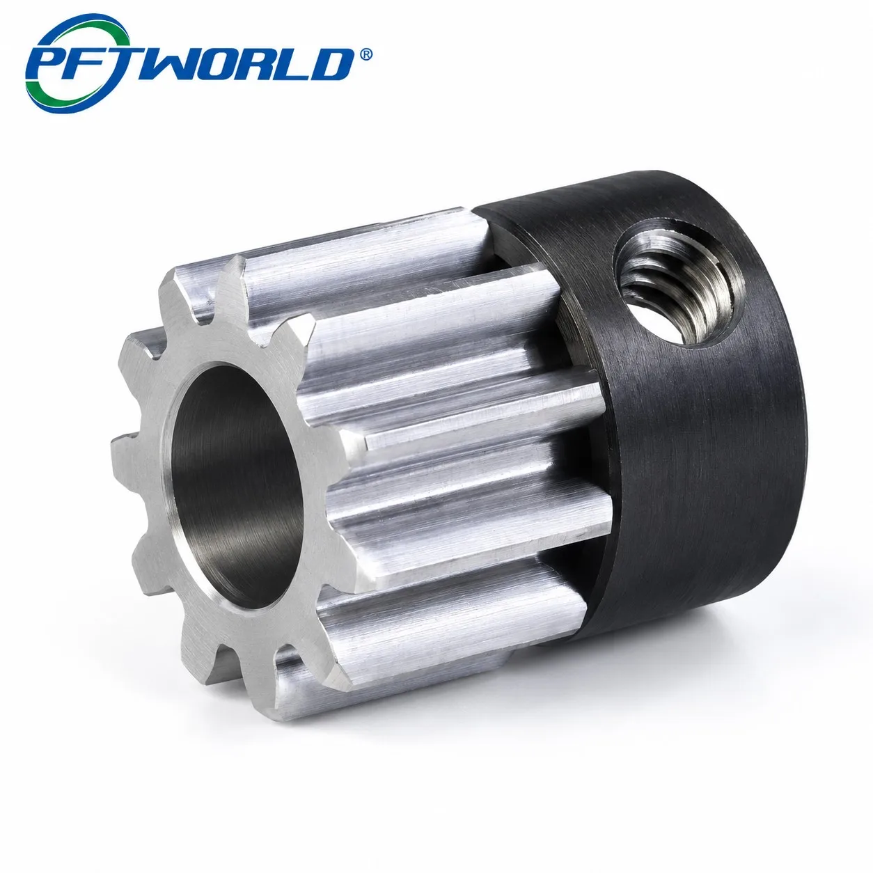
Precision CNC gear components are the backbone of modern motion-transmission systems, from desktop robotics to industrial automation lines. Unlike stamped or die-cast gears, CNC-machined gears are cut directly from solid billet using multi-axis milling, hobbing, or wire EDM, which allows engineers to hold tight tooth-profile tolerances while combining multiple features — such as an integrated gear-and-coupling-hub design — into a single monolithic part. This reduces assembly stack-up error and eliminates the backlash that often comes from pressed-on or bonded components. Below, we walk through the material, tolerance, and application considerations that matter most when specifying a custom CNC gear, followed by an engineer's FAQ.
Material & Surface Treatment
Material choice drives both mechanical performance and cost. Alloy steels (such as 45# or 40Cr) are the default for load-bearing teeth because they respond well to carburizing and quenching, pushing surface hardness into a durable range for long-term wear resistance. Stainless steel (303/304/316) is specified when the gear will see moisture, washdown, or mild chemical exposure, trading some hardness for corrosion resistance. Aluminum and brass suit light-duty, low-inertia applications where weight reduction outweighs wear life. The black-oxide or anodized finish on coupling hubs is not purely cosmetic — it adds a thin oxide layer that improves corrosion resistance and reduces galling between mating metal surfaces without affecting critical fit tolerances.
Tolerance Control & Machining Process
Gear accuracy is defined by several interacting tolerances: pitch diameter, tooth profile, lead, and runout between the bore and the pitch circle. Precision shops typically target tight tooth-to-tooth tolerances and low bore-to-tooth concentricity, achieved through CNC hobbing or gear-shaping for the tooth form combined with a secondary turning/milling operation for the bore, keyway, or set-screw features. Fixturing matters as much as the cutting tool — a single-setup design, where the teeth and bore reference the same work-holding, avoids the re-clamping error that is the most common cause of out-of-spec runout. Finished parts should be verified with a gear tooth vernier caliper, optical comparator, or CMM report before shipment, so the dimensional data matches the drawing rather than a general class rating.
Applications & Shaft Coupling Design
A combined gear-and-hub geometry is a common solution for motor-to-shaft power transmission in robotics, CNC equipment, conveyor drives, and automated packaging lines. A radial set-screw hole in the hub clamps directly onto a motor shaft, while the exposed gear teeth engage a mating gear or rack — removing the need for a separate coupling, key, or pin. This one-piece approach is especially valuable in compact servo and stepper motor assemblies where axial space is limited and alignment accuracy directly affects positioning repeatability. Engineers should confirm bore diameter, set-screw thread, tooth count, module/pitch, and pressure angle up front, since these parameters determine whether the gear will mesh correctly with existing drivetrain components.
Frequently Asked Questions
What tolerance can CNC machining realistically hold on a small gear?
For gears under roughly 50 mm diameter, most shops can reliably hold tight tooth-to-tooth tolerance and bore concentricity using a single-setup process. Even tighter tolerances are achievable but typically require grinding as a finishing step, adding cost and lead time — confirm whether your application truly needs grinding-grade accuracy before specifying it.
Should I choose alloy steel or stainless steel for a load-bearing gear?
Choose carburized and quenched alloy steel when wear resistance and load capacity are the priority in a dry, controlled environment. Choose 303/304/316 stainless when the gear is exposed to moisture, washdown, or mild chemicals, accepting lower surface hardness for corrosion resistance and reduced maintenance.
Does the black oxide or anodized finish change the part's dimensions?
Black oxide adds only microns of conversion coating and does not meaningfully change critical dimensions, so it is safe on finished-tolerance bores and threads. Anodizing on aluminum adds slightly more thickness, which should be accounted for on tight press-fit or threaded features.
Can a one-piece gear-and-hub design handle the same torque as a separate coupling?
In most cases it performs better. Because the gear and hub are machined from one billet, there is no bonded or pressed joint to fail under cyclic torque, and clamping force is applied directly against a solid body. The limiting factor becomes set-screw thread engagement and shaft material, not the gear-hub interface.
How is gear tooth accuracy actually verified before shipment?
Reputable suppliers check tooth thickness and profile with a gear tooth vernier caliper or optical projector during production, then confirm bore-to-tooth runout with a CMM report for critical orders. Ask for this inspection data alongside the parts — drawings alone don't guarantee as-built accuracy.
What information do I need to provide for a custom CNC gear quote?
At minimum: module (or diametral pitch), number of teeth, pressure angle, bore diameter and tolerance, material, surface treatment, and any coupling features such as keyway or set-screw hole. A 2D drawing or 3D CAD file speeds up DFM review and quoting significantly compared to verbal specs alone.
Need a Custom CNC Gear Component?
Share your drawing or application details and our engineering team will review fit, tolerance, and material options.
Request Engineering Review