 EN
EN


Welded C45 Brackets: Why Does Powder Coat Blister?
Welded C45 brackets look like the simplest item on a support frame drawing, and that is exactly why their failures arrive so late. Job 260627004 came to us in August 2025 from a maker of ductwork support frames whose earlier supplier had delivered arms that measured well on the bench and failed on the frame: the bar came off the welding bench bowed by about 0.6 mm, the socket face tipped out of square so the arm would not seat flat, and the light gray powder coat lifted in a thin line along every weld within the first weeks in service.
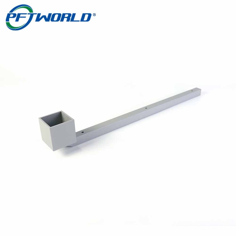
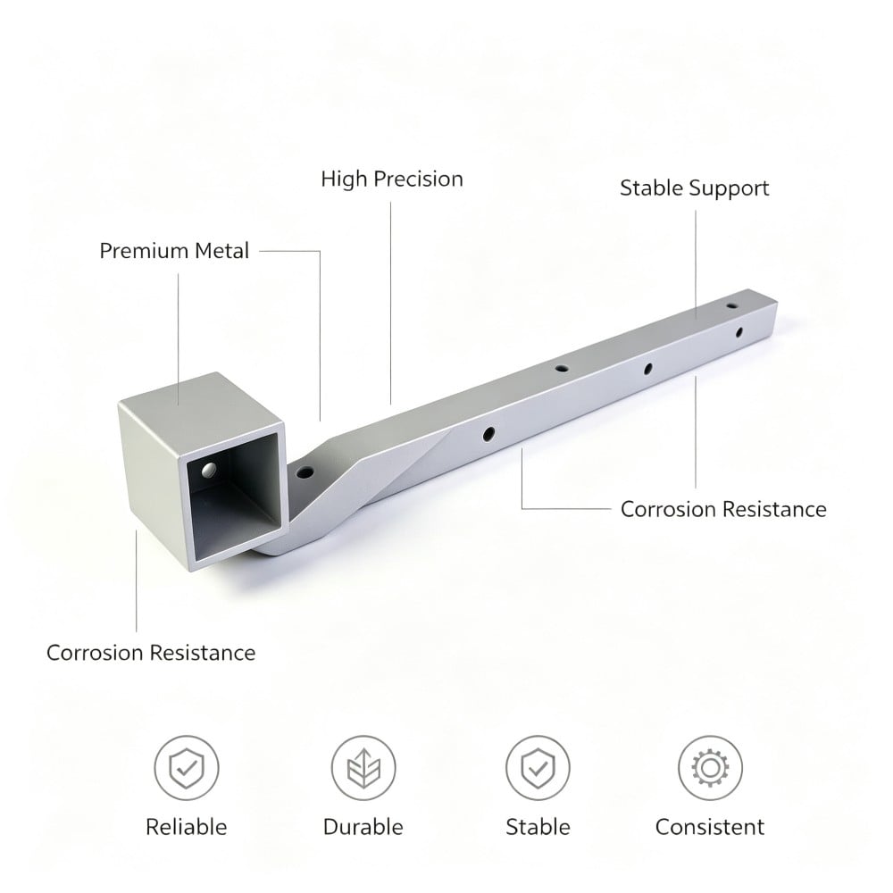
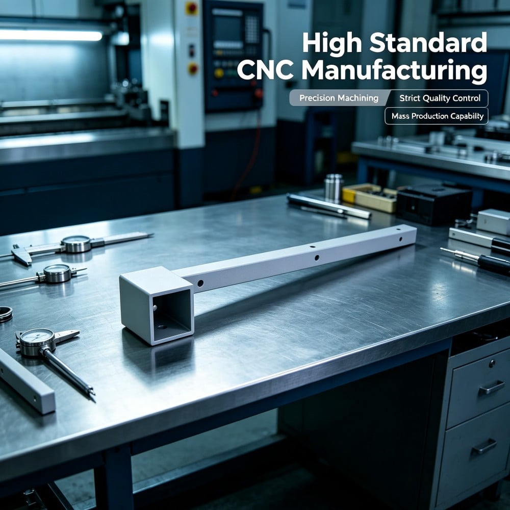
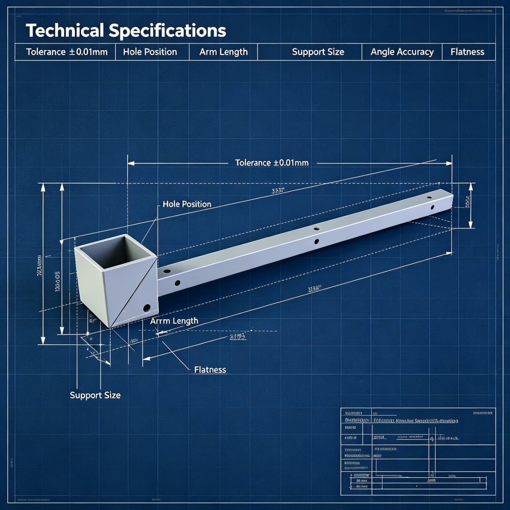
The welded C45 brackets in the photographs are the production parts from the order that followed: a 400 mm bar with three mounting holes at equal pitch, a 50 mm square socket welded to one end, and a 45 degree mitered joint where the two meet, ground flush and coated light gray. Neither welding nor coating is hard on its own. The difficulty is that the two processes fight each other, and the fight surfaces on the finished coating where the buyer sees it first.
What this bracket has to do?
Three jobs, and only one of them is about strength.
The socket is the locating feature. A mating square member slides into it and the arm then stands in a fixed relationship to the frame, so the socket must present a true, square, coated face. On this part the socket is a hollow square section, 50 mm across and 50 mm deep, welded to the end of the bar.
The bar carries the fixing. Three holes on equal pitch take the fasteners that hold the arm to the frame, which means the holes have to sit in line with the socket, not merely in line with the bar as it happened to come off the bench.
The joint is cosmetic as well as structural. The mitered joint spreads the load over a longer weld line and lets the transition from bar to socket look continuous once the weld is ground flush and coated. That cosmetic requirement is what turns a welding problem into a coating problem: a surface that is not sealed cannot be made to look seamless, and any gas still inside the weld will find the coated surface and leave through it.
The two failures that arrive together
Welding pulls the bar, and the pull stays hidden
Welding puts a concentrated heat input into a small volume of steel. The weld pool and the surrounding zone cool and contract against colder metal, and the metal that has to yield does so. On an arm welded on one side only, the contraction pulls the bar toward the welded face, and a light section 400 mm long will bow visibly from a small amount of restraint.
Two things make this worse than it sounds. First, the bar is slender relative to its length, so a small contraction shows up as a large deflection at the free end. Second, natural cooling is not symmetric, so the two sides of the joint contract by different amounts and the socket face tips. On this order the arms that failed were bowed by roughly 0.6 mm against a 0.2 mm straightness limit and had a socket face out of square by more than the 0.15 mm the frame allowed.
The reason this hides so well is measurement. A welder looks at the joint; the customer measures the whole arm. Straightness has to be checked across the length of the bar after the part has cooled, on a surface plate with a dial indicator, with the socket face checked square to the same datum in the same setup. If the check happens only at the joint, the bow is invisible until the arm is bolted on.
The coat blisters in a line, exactly where the weld is
Powder coating is a sealed film, and a sealed film over a weld behaves like a lid on a container.
Arc welding leaves porosity in and around the weld, and the pores sit under a thin skin of oxide and slag. Blasting removes the skin and opens the pores at the surface, but it does not empty them. Whatever is inside stays inside: air, moisture from the atmosphere, light hydrocarbons, and moisture introduced by the blasting operation itself. During the cure, the part and the film are both heated, and the film softens before it cross-links. Any gas expanding under the film at that moment pushes through, and the result is a pinhole or a small blister sitting on the weld line, or a ring of them.
That is why the defect appears as a line rather than at random: it follows the weld, because the weld is the only part of the surface with voids underneath it. It is also why a second supplier will not fix the problem by changing the powder brand. The film is not the cause. The gas under it is.
Two fixes address it properly. The weld zone is baked before coating so the moisture held inside the weld and the light hydrocarbons leave the part while the surface is still bare steel, and the weld line is given a second pass of powder so the film over the most porous area is built up rather than left at nominal. Anything less moves the defect from one batch to the next.
How the arm was built, step by step
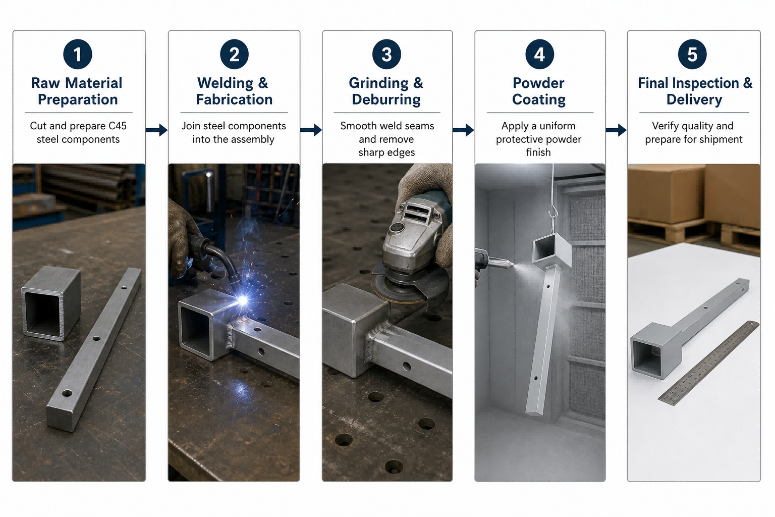
Step 1 - Cut the bar and miter the joint
The bar is cut to 400 mm with square ends and the joint end is cut at 45 degrees. A clean miter face is what makes the next step possible: two mismatched faces have to be closed by welding heat, and heat is what pulls the part.
Step 2 - Tack weld in a straightening jig
Both parts are located in a jig that holds the bar straight and the socket square while the joint is tacked. Tack welds are placed on both sides of the joint and allowed to cool before the part leaves the jig, so the geometry is set before any full weld is laid.
Step 3 - Weld in a balanced sequence
The joint is welded in alternating passes on opposite sides rather than one continuous run around the part. Balancing the sequence keeps the contraction roughly symmetric, which is what keeps the socket face square and the bar straight. The weld is taken to full penetration at the miter, since a joint that is only welded on the visible face will open under load.
Step 4 - Cool, then verify straightness and squareness
Nothing is measured while the part is warm. Each arm cools to room temperature, then goes on a surface plate where straightness is checked along the bar and squareness across the socket face. Parts outside 0.2 mm straightness or 0.15 mm on the socket face are reworked or scrapped at this stage, while they are still bare steel and rework costs a minute rather than a part.
Step 5 - Grind the welds flush
The weld is ground flush with the adjoining surfaces, the corners of the joint are blended, and any spatter is removed from the coated areas. Grinding is not only cosmetic: a proud bead overhangs and holds air at its root, and a film that has to cover an overhang will be thin at the edge and thick in the hollow.
Step 6 - Blast to Sa 2.5
The whole part is blasted to Sa 2.5. This removes mill scale, rust and welding oxide, and it opens the pores at the weld surface so the step that follows can work on them.
Step 7 - Pre-bake at 180 C for 20 minutes
The blasted parts go through a 180 C bake for 20 minutes before any powder is applied. The oven drives moisture and light hydrocarbons out of the weld porosity while the surface is still bare, which is the step that removes the blister mechanism at the source. It is also why the bake has to come after blasting and not before: blasting reintroduces moisture at the surface and opens pores that a previous bake had already emptied.
Step 8 - Coat, cure at 190 C for 15 minutes, second pass at the weld
Powder is applied to light gray RAL 7035 at 65 to 80 µm and cured at 190 C for 15 minutes. The weld line gets a second pass so the film over the most porous zone is built to the top of the range rather than left at nominal.
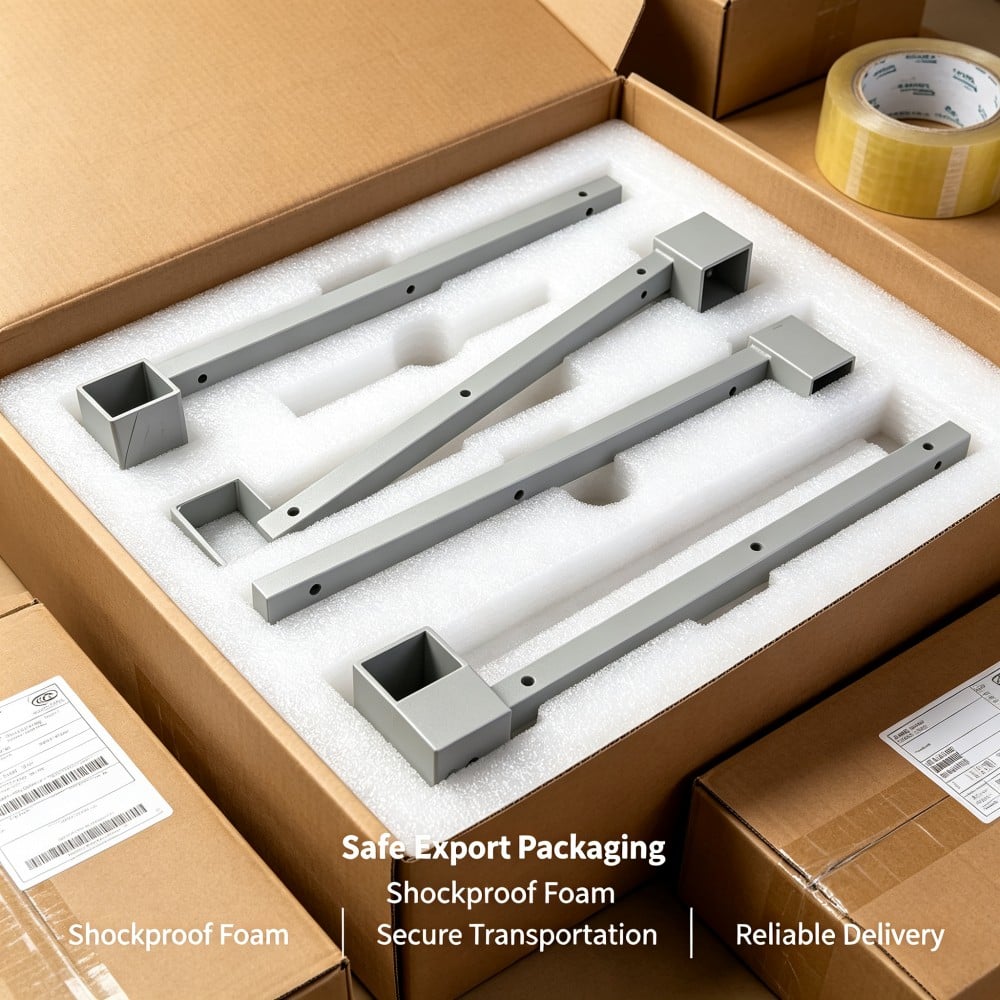
A final inspection then covers film thickness, adhesion to ISO 2409, and a close look along each weld for pinholes and blisters. The parts that pass are packed so the coated surfaces do not rub against each other in transit.
What the 600-piece run measured
| Check | Specification | Held across 600 arms |
|---|---|---|
| Straightness along the bar | 0.2 mm | No part outside the limit after cooling |
| Socket face squareness | 0.15 mm | Held on every arm measured on the surface plate |
| Weld at the mitered joint | Full penetration, ground flush | Ground flush with no visible bead on the coated parts |
| Blast cleanliness | Sa 2.5 | Verified before each batch entered the oven |
| Pre-bake | 180 C for 20 minutes | Applied to every arm before coating |
| Film thickness | 65 to 80 µm | Inside the band, including the second pass at the weld |
| Adhesion | Gt0 to ISO 2409 | Achieved on cross-hatch tests at the weld line |
| Salt spray | 480 hours neutral, no blistering | No blistering reported at the weld line |
| Pinholes along the weld | None allowed | Zero found at final inspection |
Six hundred arms shipped on the process described above. The customer reported that the arms sat flat on the frames and that no coating defect appeared at the welds in service.
The fault we found in our own trial run
The fifty-piece trial did not fail on the weld geometry. It failed on the sequence, and the sequence was ours.
Nine of the fifty arms came out of the cure with a faint line of small blisters sitting exactly on the weld. Nothing was wrong with the powder, the film thickness or the oven temperature. We had baked the parts for degassing before blasting instead of after it, on the reasoning that the bake was a welding operation and belonged with the other welding steps. Blasting then put moisture back onto the surface and into the pores we had just emptied, and the cure did the rest.
The fix was to move the degas bake after blasting and to hold blasted parts under cover, out of the shop air, until they were coated. Between the trial and production the defect category disappeared, and it did so without any change to the powder, the film thickness or the cure cycle.
That is the useful lesson for anyone specifying this process: welding and coating are not two independent operations that happen in the same factory. They share one variable, which is what is left inside the weld zone when the film closes over it.
Preparing welded steel for coating: four options compared
| Preparation | What it removes | Pinhole risk at the weld | Adhesion | Where it fits |
|---|---|---|---|---|
| Degrease, then coat | Oils and handling soil only | High, and pores stay full of gas and moisture | Poor on welds, and the film lifts at the weld line | Smooth parts with no weld in the coated area |
| Blast to Sa 2.5, then coat | Mill scale, rust, welding oxide; opens surface pores | Medium to high, opened pores still hold gas | Good on sound metal, thin over porosity | Simple welded parts in dry indoor service |
| Blast, degas bake at 180 C, then coat | As above, plus moisture and light hydrocarbons driven out of the porosity | Low | Good, including at the weld line | Welded parts in any humid or outdoor service, the sequence used here |
| Blast, phosphate, degas bake, then coat | As above, plus a conversion layer on the steel | Low | Best, and it protects the cut edges | Parts that see salt spray, condensation or edge wear |
The fourth option costs more per part and is the right answer when the arm will live outdoors or in a washdown area. For indoor frame work, the third option is normally enough, and both of them depend on the bake sitting in the right place in the sequence.
FAQ
Why does powder coat blister in a line along a weld?
Because the weld is the only part of the surface with voids under it. Welding leaves porosity filled with air, moisture and light hydrocarbons, and the film closes over it before the cure heats everything up. The film softens before it cross-links, so the expanding gas pushes through and leaves pinholes or blisters along the weld line rather than at random.
Can welding distortion be removed after coating?
No. Straightening a coated part damages the film at exactly the place the customer will look at, and heat used for straightening will damage the film and the adhesion underneath it. Distortion is removed before coating, by welding in a jig with a balanced sequence and by checking straightness and squareness after the part has cooled to room temperature.
Do welds have to be ground before powder coating?
Not always for function, but on a visible joint they should be. An unground bead overhangs and holds air at its root, which gives the film a thin edge and a hollow, and the bead also tells the buyer that the joint was left as welded. On this part the welds are ground flush because the mitered joint is meant to read as one continuous surface under the coating.
How do you check coating adhesion on a welded part?
Cut a cross-hatch through the film into the weld and the adjoining steel, apply the tape pull of ISO 2409, and rate the result. Doing it on the weld rather than on flat metal is the whole point: flat areas will pass on almost any preparation, and the weld line is where an adhesion failure shows up first. On this order the weld line rated Gt0.
What to put on your drawing
Six lines on the drawing prevent most of the argument:
1. Give straightness as a number along the full length of the bar, with a datum, not as a note about good workmanship.
2. Give squareness of the socket face as a number, in the same datum as the straightness call.
3. Say whether the joint welds must be ground flush, and where they must stay as welded.
4. State the blast grade, and state whether a degas bake is required before coating.
5. State the color reference, the film thickness band, and the adhesion class you will accept.
6. Say whether the inside of the socket needs the same film coverage as the outside, since coating the interior to full thickness changes the fit of whatever slides into it.
A welded arm is a joint, a heat treatment and a coating stacked on top of one another, and each layer can undo the one below it. Specify them as one sequence and the part is ordinary work: a bar that stays straight, a socket that seats flat, and a coating that stays smooth along the weld for years.