 EN


Precision CNC Machined Gear Shaft Components
Precision CNC Machined Gear Shaft Components
A technical overview of process parameters, failure modes, and the questions engineers ask most before releasing a gear shaft drawing to production.
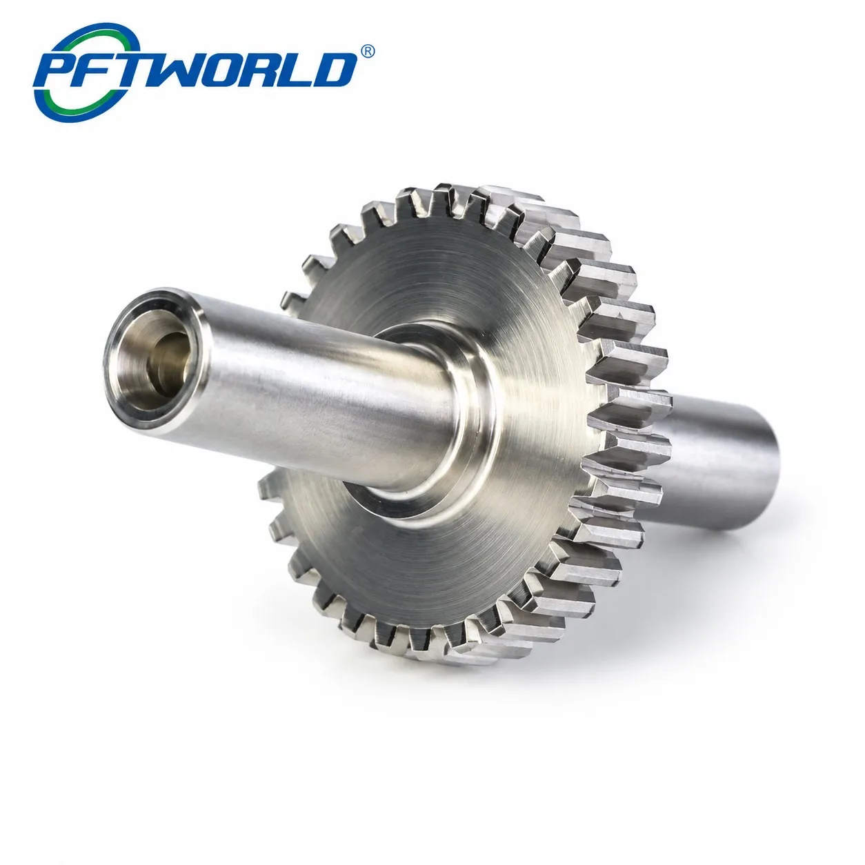
A gear shaft combines a shouldered shaft with an integral spur gear cut from the same blank. Machining both features in one turn-mill setup removes the concentricity error a pressed-on gear would introduce — the detail that matters most in high-RPM or low-backlash drivetrains.
Typical specification range for stainless and alloy steel gear shaft components:
The shaft-to-gear transition needs a relief groove sized to the hobbing or milling cutter radius. Omitting this at the drawing stage is the single most common cause of a rejected first article — catching it in DFM review avoids a re-cut sample and a lost production slot.
Frequently Asked Questions
What tolerance can a CNC gear shaft hold?
Production parts typically hold ±0.005mm on bore and shoulder diameters; gear tooth profile is controlled by AGMA/DIN accuracy class rather than a linear tolerance.
Does stainless gear shaft need secondary hardening?
303/316 stainless is usually finished as-machined for corrosion resistance. Carbon or alloy steel gear shafts generally require case hardening for wear-critical duty cycles.
What is the lead time from drawing to sample?
DFM review plus first-article machining typically runs 5–10 working days, depending on gear complexity and material lead time.
Can you prototype a single piece before mass production?
Yes. Prototypes run on the same turn-mill equipment used for production, so fit and gear mesh can be validated before any tooling commitment.
Have a Gear Shaft Drawing to Review?
Send your tolerance and material callouts for a free DFM check and quote.
Request DFM Review & Quote