 EN
EN


Brass Manifold Blocks: Why Ports That Check Still Leak
What a manifold block has to do
Three jobs, and only the first one is visible on the outside.
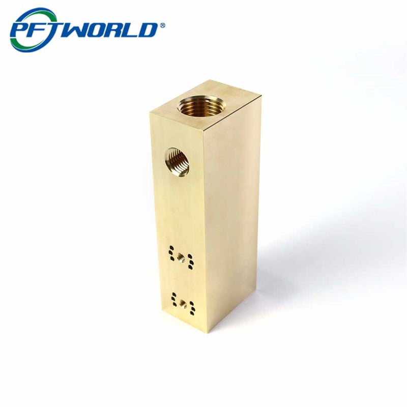
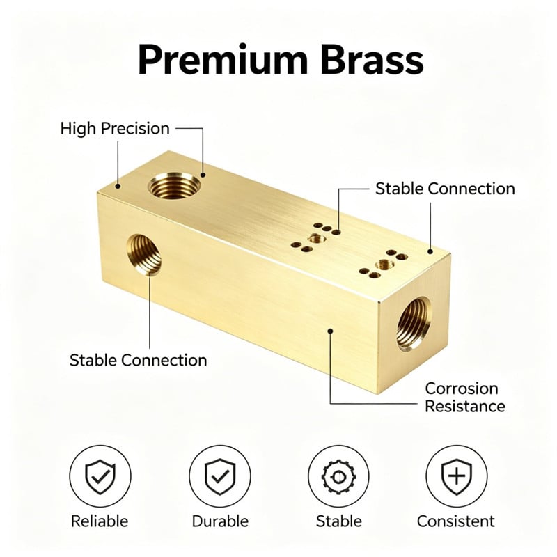
It distributes. A manifold block replaces a tree of tees, nipples and fittings with one solid part, so the ports have to sit in the positions the schematic expects and the internal passages have to reach between them.
It seals. Every threaded port is a pressure boundary, and the seal is made by the thread form, the depth the fitting reaches, and the squareness of the port face to the fitting axis. A port that is dimensionally perfect but tapped at a slight angle will hold a fitting that looks seated and weeps under pressure.
It locates. The mounting patterns on the side faces fix the block to a bracket or a valve base, so the patterns and the ports share a bracket. When a pattern is drilled in one setup and the ports are tapped in another, the two only agree by luck.
Why every port can be in tolerance and the assembly still leak
A port is checked on its own face, but the assembly only cares about the relationship between faces
A port is verified with a thread gauge, a depth check and a squareness check, all measured against its own face. Every one of those checks can pass on every port in the block, and the block can still be wrong, because none of them says anything about how the ports on different faces sit relative to each other.
The assembly is what ties them together. A fitting runs into the top port, a second fitting runs into the side port, and a valve base bolts to the front pattern. If the top port and the side port are each square to their own face but the two faces are not quite parallel or not quite square, the fittings end up leaving the block in directions nobody intended. The line is assembled by force rather than by fit, and the leak appears at whichever joint is least able to absorb the error.
That is why the drawing call that matters most on a manifold block is often the one that is missing: the geometric relationship between the faces that carry ports.
Every re-clamp is a chance to rotate the bracket
Milling all six faces and then machining features on five of them is a sequence of setups, and every setup needs a datum. If each face is machined from a datum established on that face, then each face is a small, self-consistent world, and the errors between the worlds accumulate invisibly.
The alternative is to carry one bracket through the whole job: face and square the stock once, then machine as many faces as the fixture allows before re-clamping, and when a re-clamp is unavoidable, pick it up from the same machined datum rather than from a fresh surface. On this order the top ports and one side pattern came off in the same clamping, the opposite pattern and the remaining port came off a second fixture that referenced the first setup, and the block was finally squared to the same primary datum.
The practical consequence is that a block with a modest number of ports should be machined in as few setups as the geometry allows, and the fixture design, not the machine, is what decides whether the ports agree.
Two fittings tightened into two faces is the test that finds it
The leak rarely shows up at the machine or at the bench. It shows up when a fitting is torqued into a top port and another into a side port, because tightening the second one applies a load to the first joint through the block.
If the two port axes are not square to one another, that load has a component the joint was never designed to take, and the assembly twists as it is tightened. The symptom the customer sees is a fitting that will not come up tight without force, or a joint that weeps under pressure and passes a static bubble test. It is also, in practice, the reason a batch of blocks can be accepted by inspection and rejected by the assembly team on consecutive weeks.
The second failure that hides inside: burrs where the passages meet
The burr ring sits where two drills cross
Every drilled passage leaves a burr where it breaks out, and a cross-drilled block has more of these than the outside of the block suggests. Where two passages intersect inside the material, the second drill breaks into the first and leaves a burr ring hanging on the inside wall, right in the path of the fluid. Nobody sees it, because the intersection is buried in solid brass and no probe reaches it.
That ring causes two distinct problems. It is a place for debris to collect and later release, which is what puts brass chips into a line weeks after commissioning. And it reduces the effective flow area exactly where the flow has to turn, which shows up as a pressure drop that nobody can explain from the drawing dimensions.
Why washing after machining does not remove it
Washing removes loose chips and coolant. It does not remove a burr that is still attached to the wall, and it does not reach the back of a burr ring that has folded into the passage. A block can come out of a perfectly good wash, pass a visual check of every port, and still hold a burr that will shed material once it sees flow and pressure.
The fix is to deburr the intersection deliberately rather than to rely on cleaning. On this order the passages were drilled in an order that pushes each breakout toward a port that can be reached, the intersections were deburred through the ports with a controlled pass, and the release criterion for shipping was a flush test rather than a visual check.
How the blocks were made, step by step
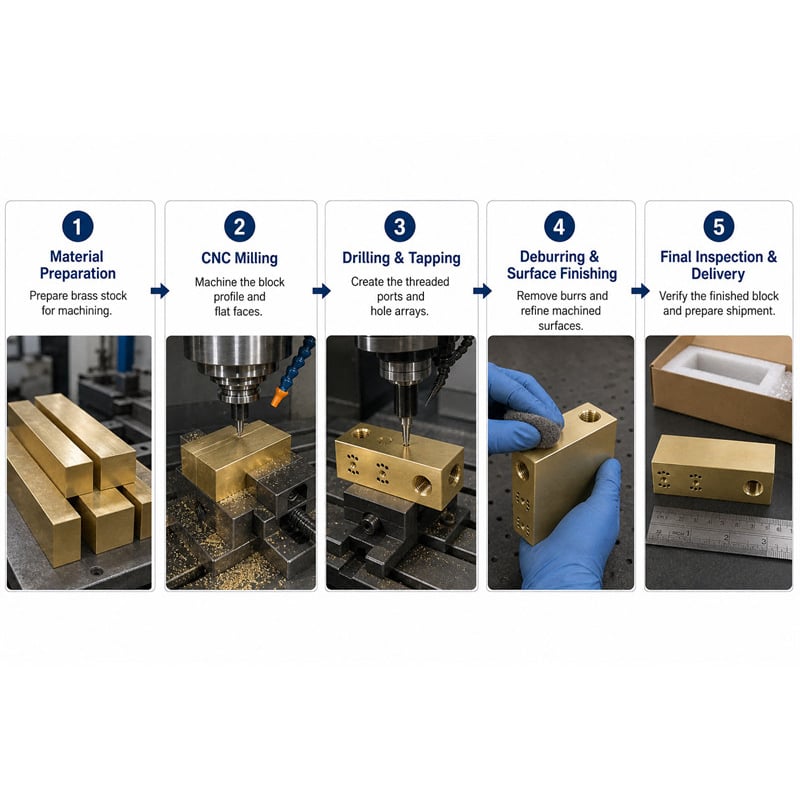
Step 1 - Face and square the stock from one primary datum
The bar is faced and squared so that all six faces come off one primary datum, with the faces square and parallel to each other. This datum is what every later port and pattern is positioned against, so it is established once and reused rather than re-created.
Step 2 - Machine the top face and end face in the same clamping
The two faces that carry the largest ports are machined in one clamping so the two port axes are cut relative to a single setup. The ports are positioned from the primary datum, not from the face they happen to sit on.
Step 3 - Drill the internal passages in a planned order
Where the drawing calls for interconnected passages, they are drilled in an order that controls where each breakout lands, so that a burr the second drill raises at the intersection ends up somewhere a deburring tool can reach rather than deep inside the block.
Step 4 - Deburr the intersections through the ports
Each reachable intersection is deburred through a port with a controlled pass, so the burr ring is cut away instead of being folded over. This is a separate operation with its own time allowance, not a step inside the wash.
Step 5 - Tap every port square to its face and to a controlled depth
Threads are tapped square to the face they sit in and to a controlled depth, so a fitting reaches its seat with the full thread engaged and no short engagement at the bottom. Port thread standard, size and count follow the drawing for each part number; the shop controls the tap, the depth and the squareness rather than assuming a standard.
Step 6 - Machine the mounting patterns and the counterbores from the primary datum
The mounting patterns and the counterbored port seats are machined from the same primary datum as the ports, so the patterns, the counterbores and the port axes all share a bracket instead of each being true to its own face.
Step 7 - Wash, then flush the passages and check what comes out
The block is washed and then flushed, and the flush is passed through a filter so the material that comes out can be examined rather than assumed away. The shipping criterion is what the filter shows, which is a check that can actually be repeated.
Step 8 - Inspect the block as an assembly, not only as a set of features
Final inspection covers thread gauges on every port, port squareness to its face, counterbore depth, pattern position, face squareness and parallelism, and the flush result. The point of the list is the last item: a port that passes on its own face still has to pass as part of a network.
What the 1,500-piece run measured
| Check | Specification | Held across 1,500 blocks |
|---|---|---|
| Six faces | Square and parallel, from one datum | Machined off the primary datum on every block |
| Port threads | Per drawing, gauged | Go and no-go checked on every port |
| Port squareness to face | Per drawing | Tapped square so fittings run in true and seat to depth |
| Port depth | Controlled depth | Fittings seated with full thread engagement |
| Mounting patterns | On position, from the primary datum | Every valve base bolted up without re-drilling |
| Counterbores | Common depth | Fitting heads sat flush and level |
| Thread condition | Clean, no burrs | Deburred and gauged before packing |
| Passages | Washed and flushed, chip-free | Filtered flush showed no material on release |
| Finish | Natural gold satin | Consistent face to face |
Fifteen hundred blocks shipped in 20 days, and the customer reported that the line went together without re-drilling, with fittings that seated to depth and sealed.
The fault we found in our own trial run
Our first fifty blocks passed every check on the inspection sheet, and one of them still failed the flush test.
The block in question had been through the same wash as the rest, and every port passed its thread gauge. When we flushed the passages through a filter, the filter caught a small amount of brass, and sectioning showed why: the deburring pass had been run through the two ports the drawing shows, but one intersection further along the internal passage could not be reached from either of them, and the burr ring there had been folded over rather than cut away. Washing moved it around instead of removing it.
Three changes went into production. The drilling order was revised so that particular intersection is broken out from the opposite direction, which puts the burr where the deburring tool can reach it. The flush test with a filter replaced the visual check as the release criterion. And the drawing note on passage reachability was added to our DFM feedback, so a customer who specifies an unreachable intersection hears about it before the parts are made rather than after.
Between the trial and the production run, the flush test stopped finding material, and the small-chips complaint that had followed this part number for two years disappeared with it.
Three ways to hold the ports to one bracket, compared
| Approach | How the bracket is set | Cross-face agreement | Setup cost | Where it fits |
|---|---|---|---|---|
| Machined from one datum with as few clamps as possible | Face and square once, then machine every reachable face from the primary datum before re-clamping | Best, because the ports are cut relative to a single bracket | Highest fixture cost, lowest risk | Blocks with ports on several faces, the approach used here |
| Machined in two setups from a dedicated fixture | The second setup picks up from a machined datum rather than a fresh face | Good, provided the fixture references the first setup and is checked between batches | Moderate; the fixture has to be maintained | Blocks where the geometry or the machine travel rules out one clamping |
| Each face machined to its own datum | Every face is a self-consistent world | Poor, and the error is invisible until assembly | Lowest setup cost, highest rework cost | Simple plates with features on one or two faces only |
The middle row is where most lost batches come from, and it is not a machining problem. A fixture that has drifted out of position still produces ports that are each square to their own face, and only the assembly can show it.

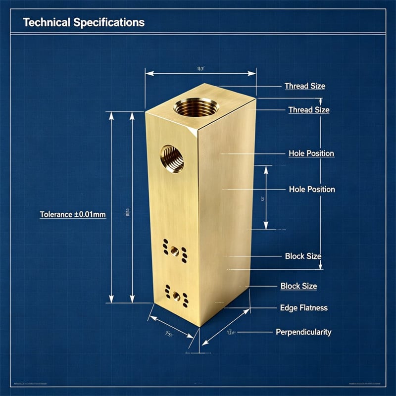
FAQ
Why does a brass manifold block leak when every port passes inspection?
Because port inspection checks each port against its own face, and the leak is caused by the relationship between ports on different faces. Two fittings torqued into two different faces load each other through the block, so any error in the angle between the two port axes turns into a force the joints were not designed to take. The block has to be checked as a network, not as a list of features.
Does a milled manifold block need a deburring pass through the passages?
Yes, separately from washing. Washing removes loose chips and coolant; it does not remove a burr that is still attached to the wall at a passage intersection or one that has folded into the passage. Burrs left at the intersections shed material into the system after commissioning and reduce the flow area where the fluid has to turn.
What port thread standard and size should the block be tapped to?
Whatever the drawing states for that part number. Port standards differ between regions and between systems, and the same block outline can be ordered with metric, unified or pipe threads, so the standard, the size and the number of ports belong on the drawing rather than in an assumption. The shop controls the tap, the thread depth and the squareness to the face.
How do you check a manifold block for chips before assembly?
Flush the passages and pass the flush medium through a filter, then examine what the filter caught. A visual check of the ports will not show a burr ring sitting inside an intersection, and a wash that leaves material behind will still look clean from the outside. Make the filtered flush the release criterion so the check is repeatable on every block.
What to put on your drawing
Six lines turn a manifold block from a guess into a part:
1. State the port thread standard, the size and the quantity per port, and say which faces they sit on.
2. State whether the block has interconnected internal passages, and if it does, whether every intersection has to be reachable for deburring.
3. Give the geometric relationship between the faces that carry ports as a squareness or parallelism call, not only the port positions themselves.
4. State the thread depth or the thread engagement the fittings need, so the seat is defined rather than assumed.
5. Name the primary datum, and say that the mounting patterns and the counterbores are positioned from it.
6. State the cleanliness the block has to meet, and whether a flush test or a pressure test is required before shipping.
A manifold block is one coordinate bracket carrying a set of threads, patterns and passages, and it fails at the joint between them rather than at any single feature. Specify it that way and the rest is ordinary milling work: faces that stay square, ports that seat to depth, valve bases that bolt straight on, and passages that stay clean for the life of the machine.