 EN
EN


Quenched and Tempered Plate: Why Does Flatness Spring Back?
What this bracket has to do?
Three jobs, and the thinnest feature carries all of them.
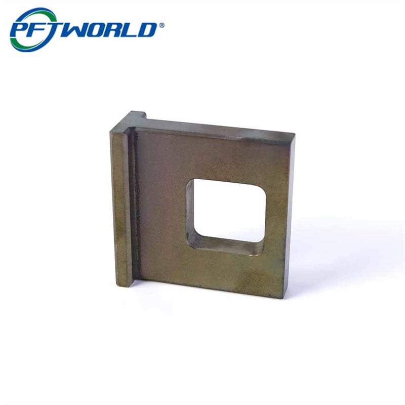
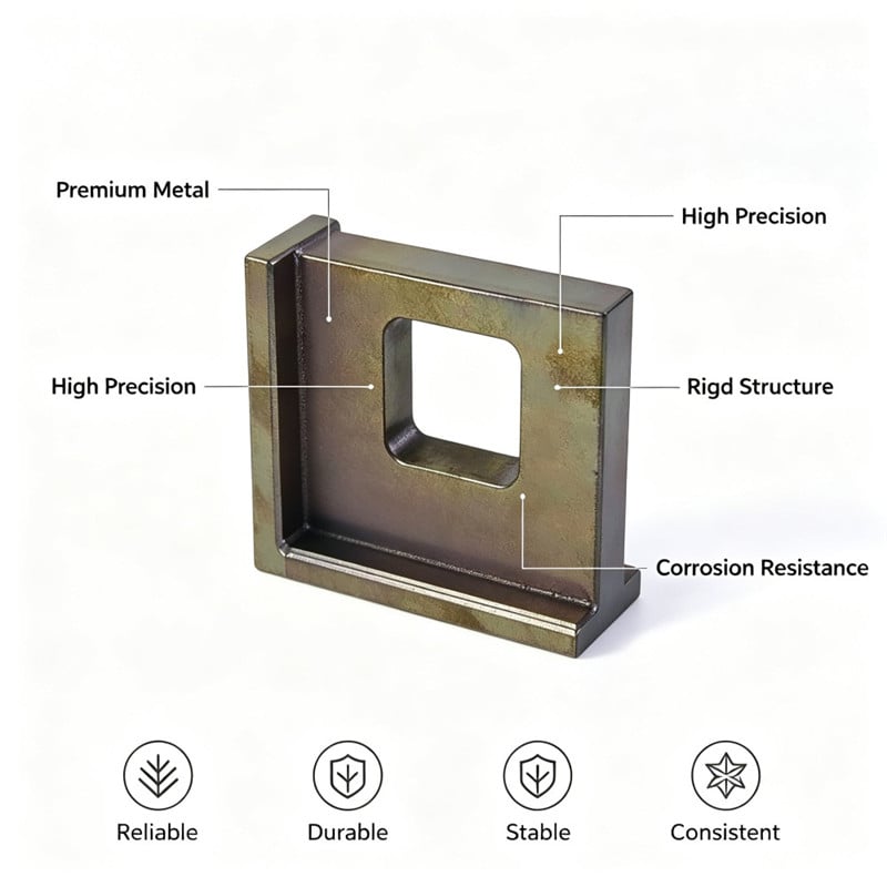
The vertical plate carries the window. The mating part passes through the opening, so the window has to be true to size and position, and the plate around it has to stay flat enough that the mating part does not bind on entry. The window walls are the thinnest metal in the part, which makes them the most sensitive to everything that happens before and after the cut.
The base flange locates the bracket. It sits on the machine bracket, so its underside is the mounting face and its internal step positions the bracket against a mating feature. If the flange is not flat, the bracket rocks and every measurement taken on the machine is taken from a moving reference.
The hardness carries the wear. The part is quenched and tempered to the hardness the drawing calls for, which is why it does not deform in service and why the window edges keep their form after the mating part has passed through them a few thousand times.
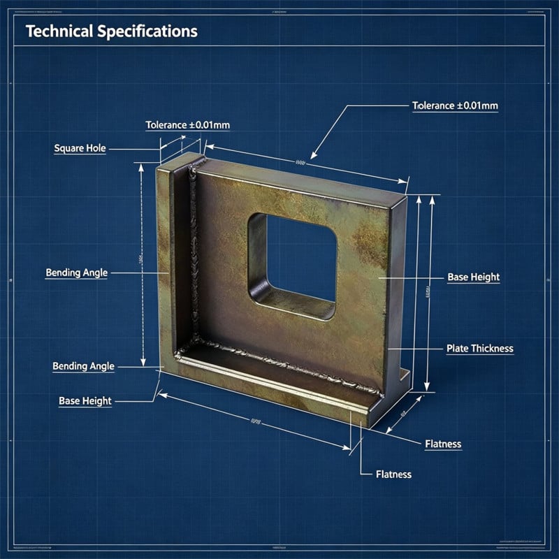
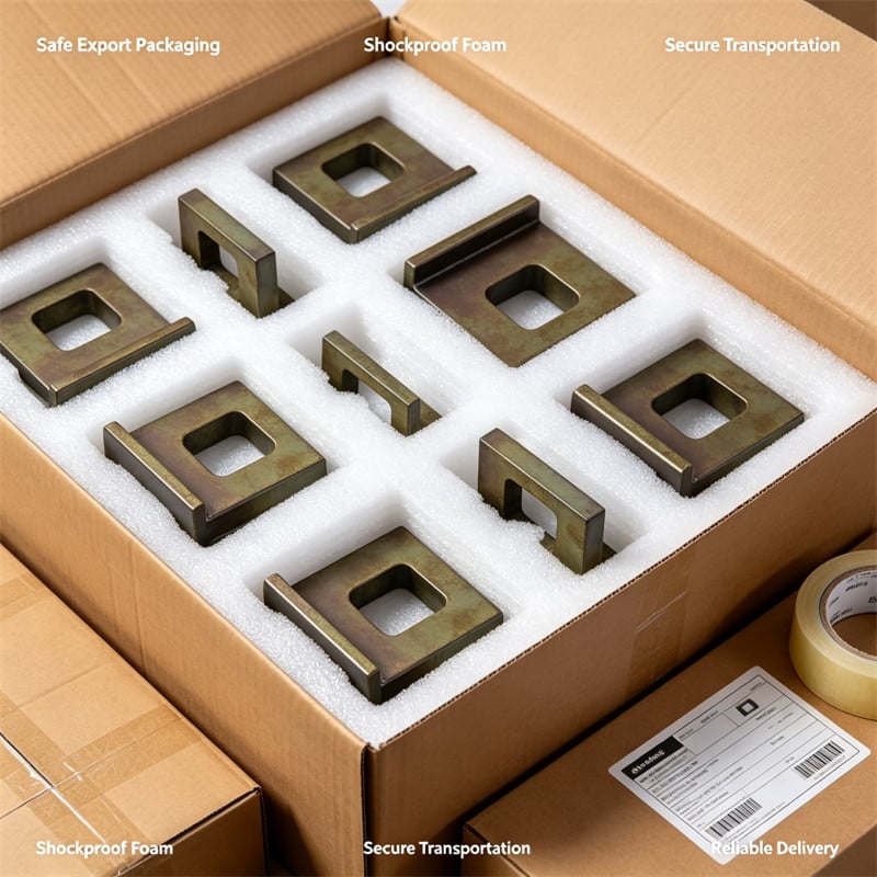
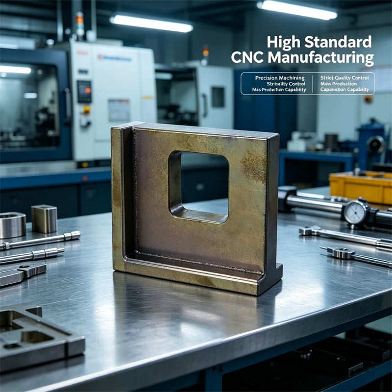
Why a thin plate is the hardest thing to hold flat after heat treatment?
The stock already has stress in it before anyone touches a machine
Rolled or drawn bar arrives with internal stress locked into it by the rolling and cooling that made it. Machining removes material from one side only, which unbalances that stress, and the part moves as the cut releases it. On a thick block the movement is absorbed by the remaining section and nothing measurable happens. On a plate a few millimeters thick, the same release bends the part.
This is why the first operation on a thin plate matters more than the last one. If the stock is roughed out with an even allowance and allowed to move before the finishing cuts, the movement happens while there is still metal to take off. If the part is machined to near-final size in one pass, the movement happens after the last cut, when there is nothing left to correct.
Heat treatment releases and re-orders that stress
Quenching and tempering is a controlled thermal cycle, and it is also the largest stress event the part will ever see. The part is heated, cooled quickly to form the hard structure, then tempered to the drawing's hardness. Each of those steps lets the internal stress re-arrange, and the part distorts slightly as it does.
The distortion is not a defect in the heat treatment. It is what the material does, and it is predictable in direction only in the broadest sense. What is controllable is whether there is still machining left to do after it happens.
The cleanup cut re-balances the stress again, and the part moves when the clamp comes off
Cutting the reference faces after tempering is what makes the bracket sit flat, but the cut itself is a stress event. Removing a skin of material from one face while the other face is untouched moves the balance again, and the part can spring as soon as the clamp is released.
This is why a machined plate has two flatness values: the one measured while the part is held, and the one measured when it is free. A single heavy finishing pass on a thin plate will produce a part that reads perfectly flat on the machine and does not read flat on a surface plate twenty minutes later, and the customer only ever sees the second number.
Clamping force flatters the measurement
A thin plate is easy to clamp flat, because clamping force is stronger than the material's stiffness. A vise, a set of low-profile clamps or even a magnetic chuck will press a bowed plate into contact with the table, and every measurement taken in that state describes the clamp rather than the part.
The practical consequence is that flatness has to be checked with the part free, on a surface plate, with a dial indicator or a height gauge, and the check has to be repeated after the part has been allowed to settle rather than immediately after unclamping, when the spring is still working.
What a window does to a thin plate?
The window walls are the thinnest section, and they chatter
Cutting a rectangular opening in a plate leaves four narrow walls, and those walls are far less stiff than the plate was before the window existed. A cutter working along them pushes them away instead of cutting, and the wall springs back into the cutter, which is chatter. Chatter shows up as a poor surface inside the window, an oversize opening, and a corner that is no longer in the position the drawing specifies.
The defence is practical rather than clever: reduce the radial engagement of the cutter, keep the cutter sharp and short, support the wall from behind where the geometry allows, and take the finishing cut on the window on both sides of the plate so the walls are loaded evenly rather than being cut from one face only.
Corner radii are where thin plates crack
A sharp internal corner is a stress concentration, and a heat-treated martensitic stainless steel is more sensitive to one than a soft low-carbon steel is. Under load, a crack starts at the corner and travels into the wall. That is why the radius on the window corners belongs on the drawing as a requirement rather than a convenience, and why it is worth checking the radius on the first part of the run and at intervals afterwards, since a worn or chipped cutter silently produces a sharper corner.
The second reason to hold the radius is that the heat treatment happens close to the feature. If the window is cut before tempering, the corner geometry goes through the whole cycle; if it is cut afterwards, the corner is machined into already-hard material and the tool has to be able to produce the radius without chipping it.
How the brackets were made, step by step?
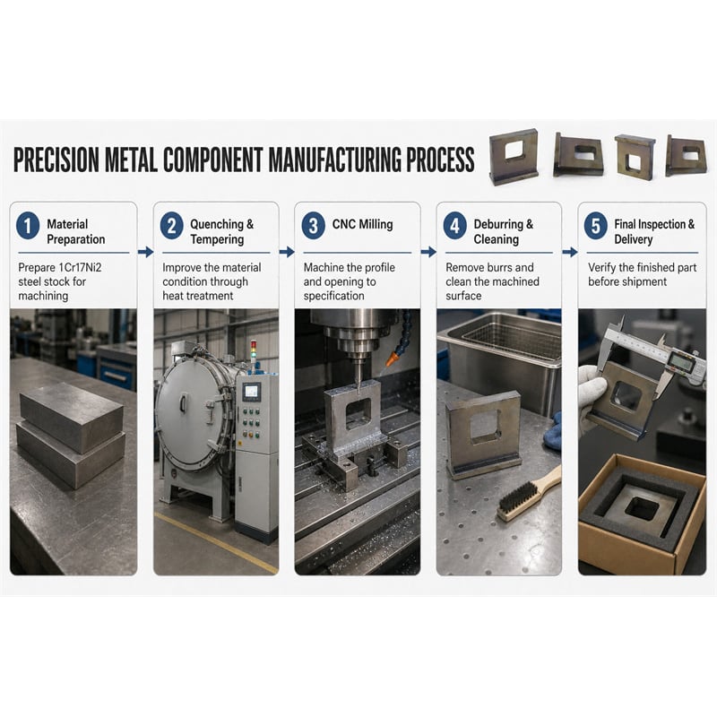
Step 1 - Rough the profile and leave allowance for a later cut
The bracket is roughed from 1Cr17Ni2 bar with an even allowance left on both faces of the vertical plate and on the base flange. The allowance is there for the heat treatment, not for the machining: the later cut has to be able to remove the distortion the thermal cycle produces.
Step 2 - Quench and temper to the drawing's hardness
The rough part goes through the full quench and temper cycle to the hardness range the drawing specifies, which is what gives the bracket its wear resistance and its resistance to deformation in service.
Step 3 - Check the hardness and record where it was measured
Hardness is checked on the part, with readings taken at more than one place so a soft spot is found rather than averaged away. Recording the positions matters: a part that measures correct at the end of the flange and soft beside the window is a different problem from a part that measures uniformly low.
Step 4 - Mill the reference faces after tempering
The faces that locate the bracket are milled after the heat treatment, so the flatness the customer measures is produced by a cut made on material that has already finished moving. The cut is taken in balanced passes on both sides of the plate rather than as one heavy pass on one side.
Step 5 - Mill the window to size and position
The window is milled with the specified corner radius, working with a light radial engagement so the walls are not pushed away from the cutter. Where the geometry allows, the finishing cut on the window is taken from both faces so the walls are loaded symmetrically and the opening ends up straight through the thickness.
Step 6 - Hold the plate thickness around the window
The thickness of the plate, and in particular the wall thickness around the window, is held to the drawing rather than left to the stock size, because that thickness is what sets how much load the window edge can take.
Step 7 - Deburr and break every edge
The window edges, the step on the base flange and the outline edges are deburred and the sharp edges are broken. A heat-treated edge burr is hard and sharp, and it will cut the hands of whoever assembles the unit.
Step 8 - Inspect the part free on a surface plate
Flatness is checked with the bracket free of any clamp, on a surface plate, together with the window size and position, the corner radius, the plate thickness and the hardness record. The order matters: a flatness number taken in the clamp is not a flatness number, it is a record of how hard the clamp was tightened.
What the 1,200-piece run measured?
| Check | Specification | Held across 1,200 brackets |
|---|---|---|
| Hardness | Drawing range, no soft spots | Checked at several places per part and recorded |
| Faces after tempering | Milled post-temper, flat | Cut in balanced passes on both sides of the plate |
| Flatness, part free | On a surface plate, unclamped | Checked with the bracket free, not in the clamp |
| Window | 18 x 12 mm, true to size and position | Mating part passed through cleanly |
| Window corners | Radiused to the drawing | Radius checked on first part and at intervals |
| Plate thickness | To drawing tolerance | Held around the window as well as across the plate |
| Base flange | Flat underside, internal step on position | Bracket sat on the bracket without rocking |
| Temper scale | Removed, even surface | Cleaned in the post-temper cut |
| Edges | Deburred, sharp edges broken | No cuts reported at assembly |
Twelve hundred brackets shipped in 24 days, and the customer reported that the brackets sat flat in the bracket, that the window took the mating part cleanly, and that no cracking appeared at the window corners in service.
The fault we found in our own trial run
Our trial run produced brackets that passed flatness on the machine and failed it on the surface plate, and the difference was the clamp.
We had set up the finishing cut with the plate clamped hard to a fixture plate, on the reasoning that a rigid setup produces a rigid part. It does not. Every trial bracket read flat in the fixture, and when we released them and checked them free, most had sprung back by more than the tolerance allowed. The clamp had been holding the bow in place while the cut was taken, and the material relaxed into a curve as soon as the pressure came off.
Two changes went into production, plus one change to the inspection. The clamping pressure was reduced to what the cut actually needs, with support under the window area instead of force on top of it, so the plate is located rather than pressed. The finishing pass on each face was split into a light roughing cut and a finishing cut with the plate allowed to sit between them, which gives the material a chance to move before the last cut rather than after it. And the flatness check was moved to an unclamped surface plate measurement as the release criterion, which is the change that would have caught the trial parts before they were ever packed.
Between the trial and production, the flatness reject rate went from visible on most parts to zero across the run.
Three sequences for a thin heat-treated plate, compared
| Sequence | How flatness is produced | Distortion risk | Hardness integrity | Where it fits |
|---|---|---|---|---|
| Rough, heat treat, finish mill | Allowance is left through the thermal cycle, then the reference faces and the window are cut on tempered material | Low, because the moving happens before the finishing cuts | Preserved, since the finish cuts are light and the part is already at hardness | Thin plates and brackets that have to be flat after treatment, the route used here |
| Mill everything, heat treat, then surface grind | The geometry is cut first and flatness is recovered afterwards by grinding a face | Medium: the window and thin walls distort in the cycle, and grinding only recovers one face | Preserved, but a hard thin plate is difficult to hold for grinding without repeating the same clamping error | Parts that are flat on one side only and thick enough to survive the cycle without support |
| Machine from pre-hardened stock | Flatness is not disturbed by a thermal cycle at all | Lowest, because there is no treatment step to distort the part | Set by the stock, so the drawing must accept the delivered condition | Simple geometry in already-hard material, where the milled features do not demand long thin cuts |
The first row costs more per part than the second, because the allowance has to be carried through the heat treatment and cut away afterwards. On this bracket the window walls made the choice for us: a few millimeters of wall around an opening will not survive a full thermal cycle and come back straight.
FAQ
Why does a milled plate warp after quenching and tempering?
Because the thermal cycle releases and re-arranges the internal stress in the material, and the part distorts slightly as it does. If the plate has already been machined to final size, that distortion has to be accepted. If an allowance was left, the distortion is cut away by the finishing passes taken after the treatment, which is why the sequence matters more than the machining parameters on a thin part.
How much material should be left for the cut after heat treatment?
Enough to remove the distortion the cycle produces on that geometry, which for a thin plate is a matter of measurement rather than a formula: treat the trial run as the measurement, check the plates free of the clamp, and set the allowance from what you find. Too little allowance leaves the bow in the finished part; too much means cutting away good material and re-balancing the stress again.
Why do thin plates measure flat while clamped but not after?
Because clamping force is stronger than the stiffness of a thin plate, so the clamp presses the bow out while the measurement is taken. The reading describes the clamp, not the part. Flatness on any thin part has to be checked free, on a surface plate, and the part is best allowed to settle before the final reading rather than measured the moment it is released.
Does milling after heat treatment reduce the hardness?
No, as long as the finishing cuts are light and the heat from cutting is controlled. Hardness is set by the heat treatment, and the cut after it removes the distorted surface layer without changing what the material is underneath. The risk in post-treatment machining is not lost hardness, it is chipping at a hard edge or a thin wall, which is why light cuts and sharp tooling matter more here than on soft material.
What to put on your drawing?
Six lines settle the flatness argument on a thin heat-treated plate:
1. State the hardness range, and say where on the part the hardness is to be checked, so a soft spot cannot hide in an average.
2. State that the mounting faces are machined after heat treatment, rather than leaving the sequence to the shop.
3. Give the window size, position and corner radius as tolerances, with the radius called out as a requirement rather than a note.
4. Give the plate and wall thickness with a tolerance, because that thickness sets the stiffness of the window edge.
5. State flatness with the part free and name the datum, and say explicitly that the check is made unclamped.
6. Say what is acceptable on the treated surface: whether the temper oxide colors are to be removed, or whether an unmachined treated surface is acceptable on the non-functional faces.
A thin heat-treated plate is a machining problem and a heat treatment problem at the same time, and the two only agree when the sequence is planned before the first cut. Get the allowance, the cut order and the unclamped check right and the rest is ordinary milling: a plate that stays flat, a window that takes its mating part, and corners that will not start a crack.