 EN
EN


Tempering After Machining: Does the Slot Close Up?
Tempering after machining sounds like the tidy way to run a locating part.
The part is already finished when it goes for treatment, the cycle gives it the hardness the drawing calls for, and nothing has to be cut afterwards on hard material. The catch is that everything the drawing fixes was set before the largest stress event in the part's life, and the features that matter most on this part are the ones with the least material around them.
Job 260414004 arrived in October 2023 from a maker of stainless locating and fixture components whose previous shop had done exactly that. The parts came back from treatment with the narrow side slot partly closed, the thin web under the central pocket no longer flat, and several tapped bores that would not take the fasteners without a fight. On the bench in the soft state, every one of those parts had measured inside tolerance.
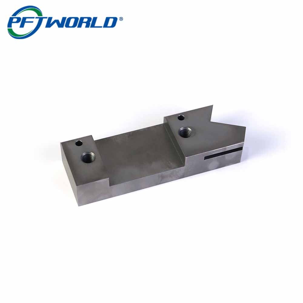
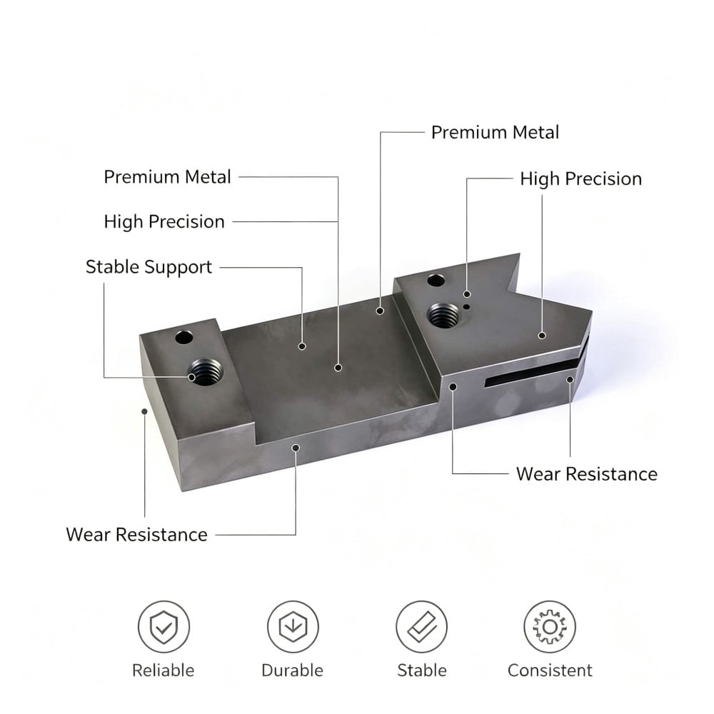
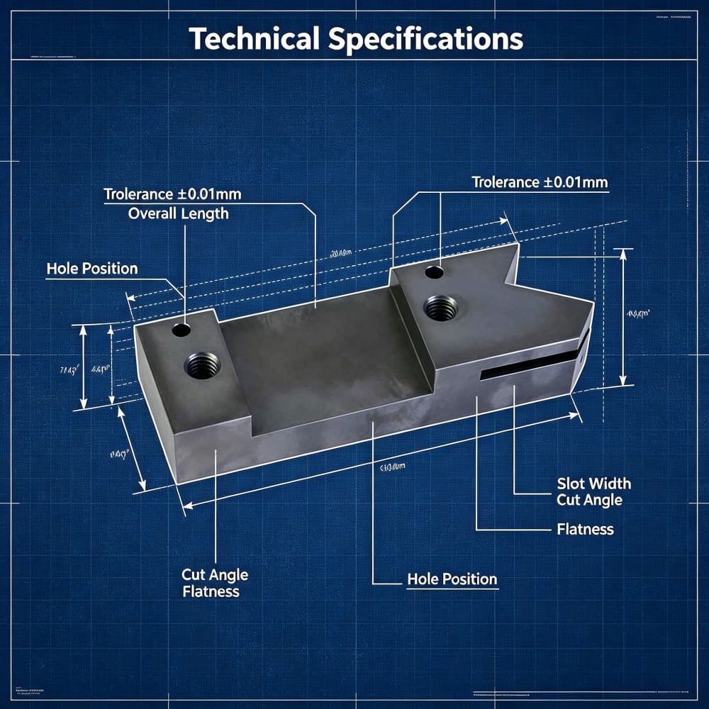
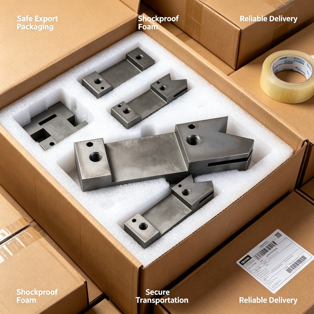
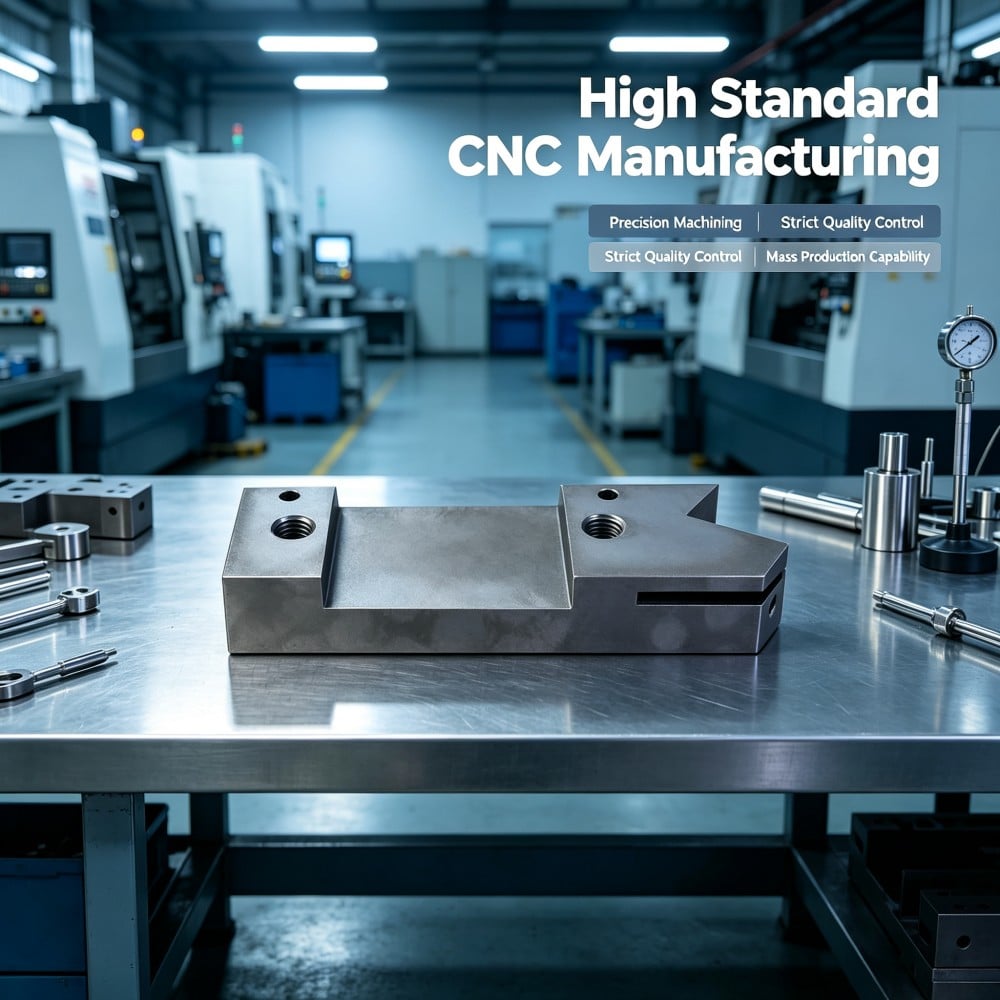
The parts in the photographs are the production run that followed: a 1Cr17Ni2 martensitic stainless locating part roughly 110 mm long and 20 mm high, milled with a central rectangular pocket about 55 mm wide that leaves a thin web as its floor, flanked by two raised end parts about 25 and 30 mm long, each carrying one tapped bore and one small pin bore, with a notched end and a narrow slot milled through the side. The matte charcoal-grey surface with its light mottling is the heat-treated finish, not a coating.
What this part has to do?
Three jobs, and the thinnest metal carries two of them.
The end parts locate. Their faces are the surfaces the fixture registers against, so they have to sit on one plane. If one end part sits higher than the other, the part rocks in the fixture and every measurement taken from it is taken from a moving reference.
The pocket web is a controlled floor. The pocket is milled to a depth that leaves a web thin enough to give the part its intended behaviour and stiff enough not to move under load. The web is the thinnest section in the part, which makes it the first thing to sag.
The tapped and pin bores are the interfaces. The tapped bore takes the fastener that holds the part down, the pin bore takes the dowel that positions it, and both have to line up with the fixture every time.
Add the narrow slot and the notched end and the picture is complete: a part whose accuracy lives in thin walls, cut before the material went through a thermal cycle.
Why milling before tempering changes the part?
Milling releases stress unevenly, and a pocket releases it worst of all
Bar arrives with internal stress locked in by the rolling that made it, and every cut re-balances that stress. A flat face milled off one side shifts the balance; a pocket milled into the middle of a part shifts it in a different way, because it removes material from the centre of the section and leaves the outside walls to carry what is left.
The result is a part that is geometrically correct when the cutter leaves it and is under a different internal load from the one it started with. Nothing has visibly happened yet. The part is simply primed to move.
The pocket and the slot remove the material that was holding the part stiff
A rectangular pocket and a narrow slot are both features that take away the metal that would otherwise hold the part straight. Before the pocket is cut, the part is a solid section and the walls are restrained by the material beside them. After the cut, the web is a thin floor and the two lands either side of the slot are free to move relative to one another.
That is the whole point of the features, and it is also what makes the sequence matter. A feature that frees the structure has to be cut on a part that has already finished moving, or the movement it allows happens later, on a finished part.
The thermal cycle finishes the movement the cutter started
Quenching and tempering is a controlled thermal cycle and, for a part like this, the largest stress event it will ever see. Heating lets the internal stress re-arrange, the quench locks in the hard structure, and the temper brings the part to the hardness the drawing calls for. Each stage gives the material another chance to settle into the shape it wants.
On a solid part the movement is absorbed by the remaining section. On a part with a thin web and a narrow slot, the sections that move are exactly the ones the drawing tolerances, because they are the only sections free to do so.
There is no cleanup allowance left to correct it
The reason mill-then-temper feels efficient is that the finishing cuts are made while the material is free cutting, where tool life is good, the surface comes out clean, and the cuts can be taken quickly. The cost is that the part goes for treatment with nothing left to remove.
Once the cycle has run, a feature that has moved is no longer a roughing problem. The part is at the drawing's hardness, the movement is in the finished geometry, and correcting it means cutting hard material on a feature that may not have stock to spare. That is the trade the sequence makes, and on this part it is decided feature by feature rather than as a policy.
The two features that move most on a part like this
The narrow slot and its width
The slot separates two lands that were previously joined, and cutting it removes the constraint between them. In the cycle that follows, each land moves according to the stress around it, and the gap between them changes: usually closing, occasionally opening, and rarely by the same amount along the length.
The symptom at assembly is specific. A mating insert that slid into the slot on the soft part will not pass through it after treatment, and the reason is not the insert and not the drawing. The slot's nominal width is correct and its effective width is not, and a check taken in the soft state cannot see it.
The tapped bore, its flank clearance and the scale in it
A tapped bore changes in two ways at once during the cycle. The thread form distorts slightly as the material moves and as the surface reacts, which takes away the flank clearance the fastener relied on, and the treated surface leaves a thin scale in the threads that a screw has to cut through on its way in.
Both effects point the same way. A bore that accepted a screw comfortably before treatment becomes one that binds part way down, and a fitter who forces it damages the thread and blames the tapping. The tapping was correct; the bore simply belongs to a different part now.
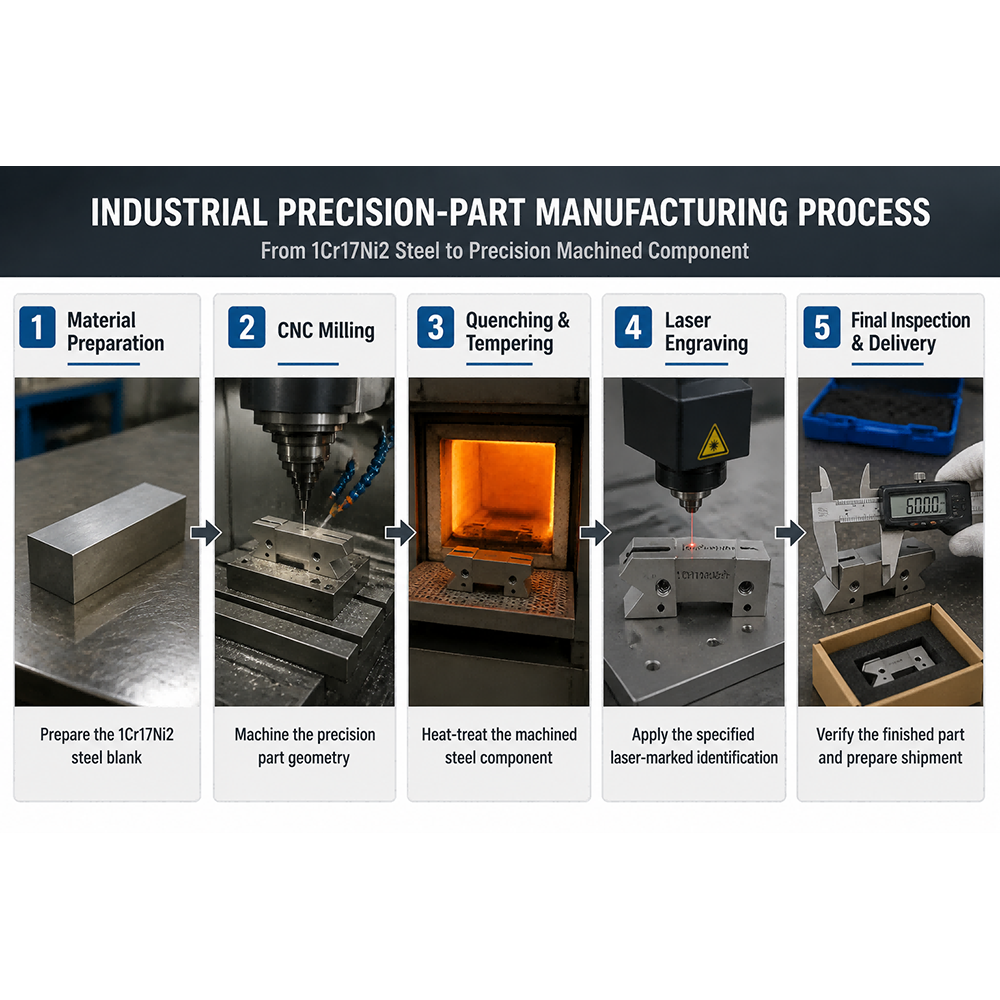
How the parts were made, step by step?
Step 1 - Rough the part and relieve the stress before finishing
The part is roughed from 1Cr17Ni2 bar with an even allowance on all faces, then allowed to settle before the finishing cuts. Removing the bulk of the material first, and letting the part respond to that before anything is cut to size, means the worst of the movement happens while there is still metal to take off.
Step 2 - Finish the faces and the pocket web in balanced passes
The faces and the pocket are milled with the stock removal balanced around the part rather than taken off one side, and the pocket floor is cut to leave the web at the thickness the drawing calls for. Cutting the pocket from the middle of the section outwards keeps the walls loaded evenly while the cutter is in the work.
Step 3 - Quench and temper to the drawing's hardness
The part goes through the full quench and temper cycle to the hardness the drawing specifies, which is what gives it the wear resistance and the resistance to deformation the application needs. This is the largest movement the part will see, and everything after it is planned around that fact.
Step 4 - Face the two end parts after the cycle
The two end parts are faced after heat treatment, in one setup so their locating faces come out on one plane. This is the operation that makes the part sit flat in the fixture, and it cannot be done before the cycle if the faces are to stay on a plane.
Step 5 - Finish the slot to width after the cycle
The slot is roughed before treatment and finished to width after it, so the last cut on the slot is taken on a part that has already moved. The wall thickness on both sides is checked at the same time, since a slot that is correct in width and off-centre will still fail to take its insert.
Step 6 - Chase the tapped bores and cut the lead-in
The tapped bores are chased after the cycle to restore the flank clearance the thread lost and to clear the treated surface out of the flanks, and the lead-in is recut so the fastener starts square. This is not re-tapping to a larger size, it is putting the thread back to the form the drawing calls for on a part that has changed since it was first cut.
Step 7 - Drill and ream the pin bores from the finished faces
The pin bores are drilled and reamed from the faced end parts, so their position is set from the surfaces the fixture uses. Doing this after the cycle is what stops the dowels from seating off-square.
Step 8 - Deburr, then inspect the part as it will be used
Every milled step, the slot edges and the notches are deburred. Final inspection covers the pocket depth and web thickness, the coplanarity of the two end parts, the slot width and position, the tapped and pin bores, and the surface condition, and it is carried out on the finished part rather than assumed from the soft-state measurements.
What the 1,500-piece run measured?
| Check | Specification | Held across 1,500 parts |
|---|---|---|
| End parts | Locating faces on one plane | Faced in one setup after the cycle |
| To drawing depth, web flat | Web thickness held to the drawing | |
| Slot | To width, on position | Roughed before treatment, finished after it |
| Tapped bores | Fasteners start and run in by hand | Chased after the cycle, lead-in recut |
| Pin bores | On position and square, dowels seat | Drilled and reamed from the faced end parts |
| Hardness | Drawing range, even | Quenched and tempered on a controlled cycle |
| Notch and steps | To drawing | Cut and checked |
| Edges | Deburred, nothing sheds | Deburred on every step, slot edge and notch |
| Finish | Matte charcoal-grey, even mottling | Consistent across the batch |
Fifteen hundred parts shipped in 20 days, and the customer reported that the locating faces sat on one plane, the fasteners ran in by hand, the dowels seated, and the fixture went together without rework.
The fault we found in our own trial run
Our trial parts were made the efficient way: milled to size, then treated. Every trial part passed the final check in the soft state, and a number of them would not go together after the cycle.
The slot was the first tell. Sections taken across the trial parts showed the slot had closed by more than the drawing allowed, with the two lands moving by different amounts along the length, so a slot that mated cleanly on the bench no longer accepted the insert. The second tell was the tapped bores, where the fasteners started by hand and then bound part way down, on threads that had measured to form before the cycle.
Three changes went into production. The slot and the tapped bores were moved to the far side of the heat treatment, with the slot roughed before and finished after and the threads chased after. The end parts were faced after the cycle in one setup, which is what put the locating faces on one plane and gave the pin bores a stable reference. And the inspection gate was moved so the release measurement is taken on the finished part, because a check that happens before the operation that causes the movement is not a check at all.
Between the trial and production the slot and thread complaints disappeared, and the soft-state figures stopped disagreeing with the finished part.
Three routes for a part that has to be hard and accurate, compared
| Route | When the critical features are cut | Dimensional risk | Hardness integrity | Where it fits |
|---|---|---|---|---|
| Rough, temper, then finish | The faces, slot and bores are cut after the cycle, on material at the drawing's hardness | Lowest, because the last cuts are taken on a part that has already moved | Preserved, since the finish cuts are light and the part is already at hardness | parts with thin webs, narrow slots or critical bores, the route used here |
| Mill to size, then temper | Everything is cut in the soft state and the cycle is the last operation | Highest on thin and freeing features, which have no allowance and no second cut | Preserved, and the soft-state cutting is fast and clean | Simple solid parts without thin sections or close-fitting slots |
| Machine from pre-treated bar | No cycle is run after machining at all | Lowest for movement, but the stock condition has to suit every feature | Set by the delivered bar, so the drawing must accept that condition | Parts where the drawing hardness can be met from stock and the geometry is straightforward |
The middle row is the one that looks cheapest on a quote and costs most in rework. It is a legitimate choice for a solid part, and on this part the pocket and the slot make it the wrong one, because the features that free the structure are exactly the features the drawing tolerances.
FAQ
Why does a milled slot close up after heat treatment?
Because cutting the slot removes the material that was holding the two lands together, and the thermal cycle then lets each land move according to the internal stress around it. The gap between them changes, usually closing, and rarely by the same amount along the length. A slot that measured to width before the cycle cannot be assumed to measure to width after it.
Why will a tapped bore not take a screw after hardening?
Two reasons at once. The thread form distorts as the material moves during the cycle, which removes the flank clearance the fastener relied on, and the treated surface leaves a thin scale in the flanks that the screw has to cut through. Chasing the thread after the cycle restores the form and clears the flanks, and recutting the lead-in lets the fastener start square.
Should I machine before or after heat treatment?
Machine the features that free the structure after the cycle, and the bulk of the material before it. Roughing before treatment is fast and kind to tooling; finishing a thin web, a narrow slot or a critical bore after the cycle is what makes those features hold. The sequence is decided feature by feature, and any feature whose tolerance is tight relative to how much it can move belongs on the far side of the cycle.
How is a thin pocket web kept flat through the cycle?
By leaving the web with stock to spare during the roughing cuts, cutting the pocket with the removal balanced around the part rather than off one side, and finishing the web after the cycle so the last cut is taken on a part that has already settled. A web cut to final thickness before treatment is relying on the material not to move, and on a section that thin it will.
What to put on your drawing?
Six lines keep a milled and treated part from becoming a rework job:
1. State the hardness the part is to be supplied at, and say whether it is reached by treatment after machining or taken from supplied bar.
2. Name the faces that have to be coplanar and give the tolerance, so the shop can face them in one setup after the cycle.
3. Give the slot width and its position with tolerances, and say that the width applies after treatment.
4. Give the web thickness under the pocket with a tolerance, because that thickness sets how much the pocket floor can move.
5. State the thread callout and say that the bores are to be clean and full after treatment, with the fastener running in by hand.
6. Say whether the treated surface finish is acceptable as-is, or whether the mottling is to be removed from the functional faces.
Machining before heat treatment is not a mistake. Treating it as a sequence decision rather than a convenience is what separates a part that goes into the fixture from a part that comes back. Decide which features can move, put those on the far side of the cycle, and the geometry stops being a race between the cutter and the cooling.